|
|
 |
|
|
|
 |
|
This is for the Shadow Warrior version of Build. Though some of the basics remain the same as the Build Duke Nukem version for creating sectors, inserting sprites, etc.. There are some major changes which allows for greater control. The flags for both Build versions remain the same and I have placed a link to a text file you can print out.
There are a few things you'll have to take care of if you want to install Build manually. First off, all the Build files must go in the same directory as Shadow Warrior. Not an extra directory and not a subdirectory in the Shadow Warrior directory. BUILD.EXE must be in the same directory as SW.EXE and SW.GRP. Nowhere else. If 3D mode in Build displays only garbage then it is most likely not in the same directory as Shadow Warrior.
Secondly, if you use the windows File Manager or Explorer to copy the files make sure that none of the files are set to be "read-only" or "write-protected". In DOS type "ATTRIB -R" in the Shadow Warrior/Build directory to remove any read-only attributes from the files.
Finally, the BSETUP to configure Build's 3D mode will only work if you place the Dos4gw.exe file in the same directory as the BSETUP.EXE is in (your Shadow Warrior directory). Then it works. Now you can run Build in high resolution.
It is understood that you have printed out the .TXT files which came with the Build editor located in the \GOODIES\DOC directory on your CD. Keep these files close at hand when creating your maps especially the SPRITAGS, WALLTAGS, SWSOUNDS, and SWBUILD text files. It is best that you look at each tutorial. I cover some detail in one that I do not cover in some of the others. I understand that the text files are difficult to follow and this is why I created this tutorial.
Please, do not email with questions on how-to create something that I have not covered in the present tutorials. I do not have the time to give out individual tutorials.
If you have a question e-mail me.
Do not send me your maps unless I ask for it. I will only ask for them to help you through a problem that you have with your map (if I feel it is needed). If you are having a problem with a tutorial or your map then go to Map Help.

I have separated the tutorials into three categories which are Beginner, Novice, and Advanced. Try not to jump ahead of your understanding of the Build engine. Build simple, small maps at first, and by all means experiment with them. Remember, save your maps often using different names (My1.map, My1a.map, My1b.map, etc...) through the various stages.

Designed for learning the basics of the Shadow Warrior Build engine. It is best that you go over the SWBUILD.TXT file from beginning to end. Make sure that you experiment to get a good feel on how things work. This will make an excellent foundation to build on. Don't just read through it rather, work through the SWBUILD file while in Build. By just reading, you may very easily become lost or confused. It takes a lot of time now, but saves so much more time in the long haul.
|
Rooms with Archway Sectors & Textures Monsters and Stuff Door - Ceiling to Floor Door - Floor to Ceiling Door - Keyed
|
Door Linked to a Switch | Basic Elevator |

Your first concern here should be the Flags of the Build engine, and how to read them. You should have no problems in creating sectors, working with sprites, tagging , Copying and Pasting sectors, and working with textures.
| Flags of the Build Editor |
Object - Auto Turret Object - Oper Turret Elevator Teleporter
|
Dynamic Lighting Torch Spawn Items |

No head scratching allowed here. Here you learn the concepts on how to create an effect. Yes, you should be able to improve on the effect(s) with some experience. At times, you will notice that I leave out a lot of the basics and just cut down to the meat.
|
Transparent Water
|
Object - Drivable Tank Fill Pit |

Here are some of the maps that I have done. They are designed for Wangbang (DeathMatch) play. However, they can be played in Single and Multi-Player too. Check them out in Build to see how different concepts are done.
|
babsw1.zip |
babsw2.zip |
babsw3.zip |
This is where you come for help on your map. You must follow these procedures in order to recieve any help from me with your problems you are having in your map. I only work with one map and the problems on that map at a time. So, if you send me a map that I have not asked for your email will automatically be deleted by me. This is the only way I can keep order on my computer. I enjoy helping others, but I can't have a ton of maps coming to me at once.
I enjoy helping others in the creation of their maps. However, you must follow these simple procedures to recieve any help from me.

This is the basic tutorial to teach you how to create two rooms with an archway. To view this map in Shadow Warrior download rooms.zip
 Fig 1. 2D mode of a sector. |
1. In 2D mode (numeric pad ENTER toggles), make a sector by pointing the mouse at a starting point for the first wall of the sector and hit the SPACE bar. Drag the mouse where you want the first wall to end and hit the SPACE bar again. Keep doing this until you come back to the starting position to complete the sector. Make sure that you have place the white arrow inside your sector and press SCROLL LOCK for the player starting position. A brown arrow will indicate the SINGLE player starting position and will be under our white arrow at this time.
2. Go into 3d mode (numeric pad Enter), and raise the ceiling by pointing the mouse cursor on the ceiling, pressing Page Up several times while holding down the left mouse button. Make the height of the room 160 pixels height. To check the height go back to 2D mode (numeric pad Enter) place the mouse cursor in the sector and press TAB. On the lower left you will see the height of the sector.
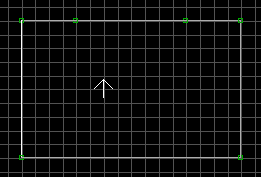 Fig 2. Insert two vertices. |
3. Place two vertices eight grid squares apart by placing the mouse cursor on the north wall and hit the INSERT key.
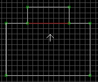 Fig 3. Adding an archway sector. |
4. Make the archway three grid squares deep (north direction). This is done by using the SPACE bar as we did in 1 above. You must connect each vertice. If you do it right the line between the two sectors will turn red.
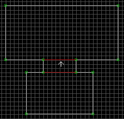 Fig 4. Adding a larger room. |
5. Make larger room connected to the archway as you did in 4 above. The line between the two sectors will turn red.
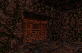 Fig 5. 3D mode view of an archway. |
6. Lower the ceiling height of the archway to 112 in height as we did in 2 above. Now you can change the textures in 3D mode by pressing "V" twice and choosing the texture(s) that you want. Also. you can shade the walls, floors, and ceilings by hitting the + and - numeric pad keys.
This is the basic tutorial to teach you how to create basic sectors and how to use textures. To view this map in Shadow Warrior download sectex.zip
I will be discussing different key functions throughout this tutorial, and to
make it easier I will color code them as follows:
Green - Will be for the numeric pad keys.
All other standard keyboard keys will be mentioned in the standard color for
this page.
The numeric pad keys are usually located on the far right side of most
keyboards. So when I have the word Enter I am
talking about the numeric pad Enter key and not the big Enter keyboard key.
It should be noted that the Enter key is used to toggle between 2D mode and 3D mode.
To save a map go into 2D mode first and press the Esc key. If you have not given your map a name yet or you want to give it a new name then press the A key (for Save As). Type in the name for your map (i.e. my1 would name your map to MY1.MAP). Do not enter the .MAP extension this is done for you. If you already have your map saved with a name and you just want to resave it then press the Esc key then S (for Save the present named map), and that's it. It is best that you save you map in various stages as you move along in the creation of your map (i.e. MY1, MY2, MY3, etc.). This way if there is a problem you can reload your prior map and try it again.
A sector is an area consisting of a floor, ceiling, and walls that are all connected. A sector can be a room, archway, door, vent shaft, window opening, desk, hallway, step, etc.. You can have sectors inside a sector (i.e. crates in a room). Sectors are what the player moves through and/or the areas that can be seen. If it is not a sector then it is void space. The sprites (i.e. weapons, items, torches, enemies, etc.) must go in sectors. Sectors will give the player a challenge with the puzzle you create that the player must move through to find the exit.
Textures are the graphics used for floors, ceilings, and walls. They are veiwed and changed in 3D mode only while in Build. Textures can be stretched, squeezed, panned, flipped, orenitated to the floor or ceiling (floor by default), copied, pasted, and shaded (probably a few more I haven't thought of at this time). Textures will give the player the feel of the level that you create.
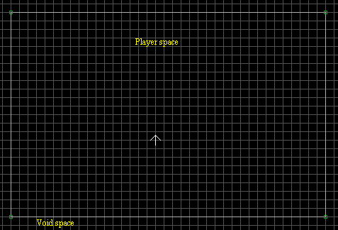 Fig 1. 2D mode of a sector. |
1. In 2D mode, make a sector by pointing the mouse at a starting point for the first wall of the sector and hit the Space bar. Move the mouse where you want the first wall to end and hit the SPACE bar again. Keep doing this until you come back to the starting position to complete the sector. Make sure that you have place the white arrow inside your sector and press SCROLL LOCK for the player starting position. A brown arrow will indicate the SINGLE player starting position and will be under our white arrow at this time. You will notice at each corner of our sector there is a little green box or dot. These are called vertices and are connection points between each wall. You will notice that these walls are white and are called single-sided walls. A single-sided wall only has player space on one side. I call the other side void space and it can never be occupied by the player or anything else. So, our single sector here as player space on the inside, and void space on the outside. To change the size of a sector, place the cursor on a vertice and press the left mouse button and drag the vertice to where you want it to go. Then release the mouse button. For this first sector I pressed the G key (in 2D mode) until I got the biggest grid squares. Then I made the sector 10 by 10 grid squares.
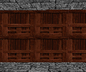 Fig 2. Raise ceiling and add new texture. |
2. Go into 3d mode (Enter toggles), and raise the ceiling by pointing the mouse cursor on the ceiling, pressing PgUp several times while holding down the left mouse button. By holding down the left mouse button the cursor no longer has to pointed at the ceiling. However, if you do not hold down the left mouse button when using the PgUp or PgDn keys, moke sure the cursor is on the ceiling or floor each time that you press one of the keys. Make the height of the room 256 pixels height. To check the height go back to 2D mode place the mouse cursor in the sector and press TAB. On the lower left you will see the pixel height of the sector. In 3D mode, place the cursor on the wall in front of you and press the V key twice. Use the PgDn and/or arrow keys and go to picnum 136. With picnum 136 highlighted press the Enter key and this texture will appear on the wall (see fig. 2). You will notice for this texture that it seems stacked for this height. We can do two things to correct this. Either PgDn the ceiling or stretch the texture. Since, we can easily PgDn it let's stretch it instead.
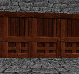 Fig 3a. Stretching vertically. |
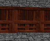 Fig 3b. Stretching horizontally. |
3. As shown in fig. 3a, stretch the texture vertically using the 8 key. The 2 key will shrink it back vertically. If you want to start over press the / key with the cursor still on the texture (of course). Use the 4 key to stretch the texture horizontally (as shown in fig. 3b), and the 6 key to shrink it back down. With the cursor still on the texture, copy it by pressing the TAB key. Now, place the cursor on the other three walls (one at a time in 3D mode) and press the Enter key. To align the textures just place the cursor on the wall you want to start the alignment with and press the . (period) key. The texture will align going to the right (clockwise). It is best that you save you map prior to the alignment. Play with it to get the desired alignment. If you want to pan a texture it is done with the same numbered keys (2, 4, 6, or 8) only this time hold down the Shift key too. I gave the ceiling a picnum of 233, and the floor a picnum of 196. Again, this is done in 3D mode by placing the cursor on the present picnum texture and pressing the V key Twice. Highlight the picnum that you need and press the Enter key. You can shade textures by using the - or + keys (in 3D mode). I shaded the ceiling and floor a little.
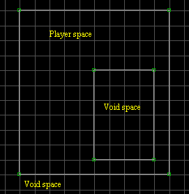 Fig 4a. Creating a pillar. |
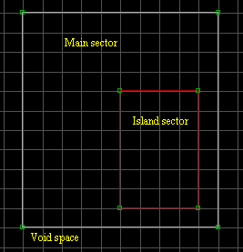 Fig 4b. Now an island sector. |
4. Using the Space bar again, I created what I term as a Pillar (as shown in fig. 4a). It is inside of our first sector and it's walls are one-sided (white). There is a void space in this area where the player can not go. If you look at it in 3D mode it will be solid walls that go from the floor all the way up to the ceiling (like a pillar). To make a pillar into a sector, place the cursor inside of it (2D mode) and press the Alt-S keys. The white lines will turn red and this type sector is called an island sector (fig. 4b) which is a valid player space. Now, if you look at it in 3D mode the pillar will be gone and you can't tell where this sector is because it looks just like it did before we added the pillar to our map.
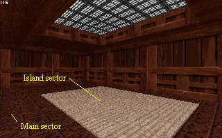 Fig 5. 3D view of the Island sector. |
5. In 3D mode, place the cursor on the floor where the Island sector is (make a guess), and press the PgUp key once. Give this floor texture picnum 3547. Now, give the sides of this Island sector the same picnum. Note, you may have to press the / key first on the sides. This is a good habit to get into on the sides of any new sector that you create. As you use the PgUp and PgDn keys to expose the sides, sometimes the textures are not at their default size. Using the / key corrects for this. Shade these sides to be darker using the - key. Ok, raise the ceiling of our island sector using the PgUp key several times (in 3D mode). Adjust the alignment of these upper sides as needed. Give the ceiling picnum 2711 for the lights texture.
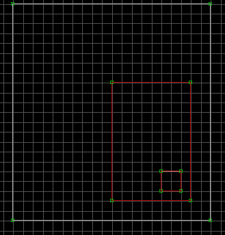 Fig 6a. Make a new island sector for a crate. |
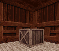 Fig 6b. 3D view of crate. |
6. As shown in fig. 6a, create another island sector inside our first island sector. I made the grid squares one size smaller then the biggest gird setting using the G key. As before, raise the floor of this new sector and use picnums 108, and 109 for the crate textures. If you need to pan the floor (top of the crate) texture use the 2, 4, 6, or 8 keys. Important, you must insert ALL island sectors in the order that I have shown you here. You can not make the crate sector first then a bigger sector around the smaller sector. In other words, when you need to have sectors inside of other sectors you work outside in not inside out. If you see a sector kind of fading in and out while playing a game this is what has happened.
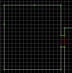 Fig 7a. Insert two vertices. |
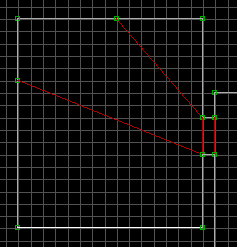 Fig 7b. Connect the vertices. |
7. In fig. 7a I created an archway and another room (different tutorial). I darken the room using the - key. I want some light to come into the room through the archway and onto the back corner. So, I inserted two vertices and then connect a vertice to the archway vertice, and did the same to the other two using the Space bar.
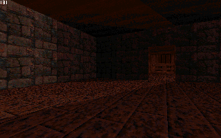 Fig 8. 3D view of the darken room. |
8. By using the + key, I lightened the floor, ceiling, and the two back corner walls. Shading can make your maps stand out. So, take the time to experiment with shading. Look around you in your house, work, etc. and carefully look at the shading of the floors, walls, and ceilings with different light effects.
This tutorial is designed to show you the easiest way to add monsters, weapons, ammo, and inventory items into your maps. It is best that you have section 3.1 of the SPRITAGS.TXT handy while inserting your monsters. To view this map in Shadow Warrior download stuff.zip (Dated 26 March 1998).
In the STUFF.MAP file you will find all of the monsters, weapons, ammo, inventory items, cracks, keys, and a few other things.
1. With the monsters you must pay attention to the palette value (Alt-P in 3D mode) if other than a value of zero. Refer to section 3.1 of the SPRITAGS.TXT for more info on the palette values for the monsters.
2. To copy a sprite, load the stuff.map into Build, and go into 3D mode. Place the cursor on the desired sprite and press the TAB key to copy it. Now, load your map and go into 2D mode. Place the cursor where you want the sprite to appear in your map and press the S key. Set the angle that you want the sprite to face during gameplay by using the < or > keys while the cursor is on the sprite. The only excemption to this angle rule is for the green Guardian Head weapon. The angle for this sprite must face in the opposite direction that you want it to face during gameplay.
3. The skill level for the monsters to appear in (on up) must be set. The default setting is for skill level 2 which is the 3rd skill level. The skill levels range from 0 to 3. To set a skill level for a monster go into 2D mode and place the cursor on the monster sprite. Now, press the F8 key, then 1. Enter a value from 0 to 3 for the monster to appear in. If for example you enter 0 then the monster will be in all of the skill levels. If you enter 2, then the monster will appear only in the two hardest skill levels (2 and 3). Note: there is no effect with weapons, ammo, or items with the skill level settings. I have strongly discussed this great error with 3D Realms and they have told me that this problem will be taken care of with Prey. Well, we will have to wait and see.
4. If you wish for a weapon, ammo, or inventory item to only appear in WangBang (DeathMatch), then use the F8 key then 2. All weapons, ammo, and inventory items appear in Multi and WangBang modes no matter if it is set for Multi play or not (no control for us).
This is the basic tutorial to teach you how to create a ceiling to floor door. To view this map in Shadow Warrior download door1.zip
 Fig 1. Archway and door. |
1. First create two rooms with an archway. In the archway, make the door by inserting four vertices (Insert key). Connect the two lower vertices using the SPACE bar. Next, connect the upper two vertices using the SPACE bar. This middle sector will be the door.
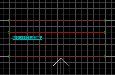 Fig 2. Inserting ST1 sprite. |
2. Make the grid smaller by pressing "G" once. Now insert a sprite in the door sector by pointing the mouse cursor in the door sector and hit "S". Go to 3D mode (numeric pad Enter) and the sprite will probably look like a gray wall tile (picnum). Place the cursor on it and press "V" twice. Now press "G" and enter 2307 and press Enter. This takes you to the ST1 sprite that we need. Now, press Enter again and we should be back in 3D mode with the ST1 sprite on the floor. Since this is a ceiling to floor door we need to flip this sprite upside down. This is done by placing the cursor on the sprite and holding down the left mouse button press "F" twice. Release the mouse button.
3. Now comes the new stuff. Referring to the SPRITAGS.TXT file go to Hitag 92 (SECT_VATOR). Place the cursor on our ST1 sprite in 2D mode and Alt-H. Now enter 92 Enter. We need a low matching tag for our door, sounds, and anything else that we want connect to this door operation. If you don't know what your next tag number should be press F5 and it will tell you the next available tag number to use. In our case it will be 1. Press Alt-T and enter 1 Enter. Now here is the real new stuff. There are TAG# and BOOL# numbers that need to address for your door to work at all. This you can see in the SPRITAGS.TXT mentioned above. To change the values of TAG# you press and hold the ' (under the ") key and the number you need to address. To change TAG3, press ' and 3 then enter the value and press Enter.
Ok, now for the BOOL#. To enter a BOOL# you need to press ; and number. The number can only be a 1 or 0 nothing else.
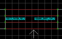 Fig 3. Inserting ST1 sound sprite. |
4. Insert another ST1 sprite next to the first one and give it a Hitag of 134 (sound spot) and the same Low tag of 1. Give TAG4 = 169 (the sound). No BOOL# need to be changed.
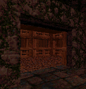 Fig 4. A 3D view. |
5. I like to move the door sector one PgDn from the height of the archway for looks. The walls on each side of the door should be stationary (there shouldn't move with the door). To do this put the cursor on the side walls of the door sector and press "O". Now If you use the PgDn and PgUp keys you will see that they don't move. If for some reason when you PgDn the door and it looks strange put the cursor on it and press "/" to set the texture to it's default size.
This is the basic tutorial to teach you how to create a floor to ceiling door. To view this map in Shadow Warrior download door2.zip
 Fig 1. Archway and door. |
1. First create two rooms with an archway. In the archway, make the door by inserting four vertices (Insert key). Connect the two lower vertices using the SPACE bar. Next, connect the upper two vertices using the SPACE bar. This middle sector will be the door.
 Fig 2. Inserting St1 sprite. |
2. Make the grid smaller by pressing "G" once. Now insert a sprite in the door sector by pointing the mouse cursor in the door sector and hit "S". Go to 3D mode (numeric pad Enter) and the sprite will probably look like a gray wall tile (picnum). Place the cursor on it and press "V" twice. Now press "G" and enter 2307 and press Enter. This takes you to the ST1 sprite that we need. Now, press Enter again and we should be back in 3D mode with the ST1 sprite on the floor. Since this is a floor to ceiling door we need to have this sprite at the height that we want the door to stop at. In this case the ceiling, put the cursor on the ST1 sprite and press Ctrl-PgUp. Now the top of the ST1 sprite is on the ceiling. However, the door will stop at the bottom of the sprite leaving a gap at the top of the door. So, we need to place the cursor on the ST1 sprite, hold down the left mouse button and press PgUp twice. Now, the bottom of the ST1 sprite is at the actual top of the ceiling, and so will be our door. The location and position of this ST1 sprite is the only difference between a floor to ceiling and a ceiling to floor door. Everything else remains the same except for using "O" in 3D mode as we did with the ceiling to floor door.
3. Now comes the new stuff. Referring to the SPRITAGS.TXT file go to Hitag 92 (SECT_VATOR). Place the cursor on our ST1 sprite in 2D mode and Alt-H. Now enter 92 Enter. We need a low matching tag for our door, sounds, and anything else that we want connect to this door operation. If you don't know what your next tag number should be press F5 and it will tell you the next available tag number to use. In our case it will be 1. Press Alt-T and enter 1 Enter. Now here is the real new stuff. There are TAG# and BOOL# numbers that need to address for your door to work at all. This you can see in the SPRITAGS.TXT mentioned above. To change the values of TAG# you press and hold the ' (under the ") key and the number you need to address. To change TAG3, press ' and 3 then enter the value and press Enter.
Ok, now for the BOOL#. To enter a BOOL# you need to press ; and number. The number can only be a 1 or 0 nothing else.
 Fig 3. Insert the ST1 sound sprite. |
4. Insert another ST1 sprite next to the first one and give it a Hitag of 134 (sound spot) and the same Low tag of 1. Give TAG4 = 169 (the sound). No BOOL# need to be changed.
5. The walls on each side of the door should be stationary (there shouldn't move with the door). If you put the cursor on the floor of the door sector and hold the left mouse button while pressing PgUp the walls on the side of the door sector shouldn't move. This is because the wall are connected at the ceiling. If the walls move then they have been connected to the floor. If so, put the cursor on the wall and press "O" again and they will be connected back to the ceiling. Now if you use the PgDn and PgUp keys you will see that they don't move. If for some reason when you PgDn the door and it looks strange put the cursor on it and press "/" to set the texture to it's default size.
This is the basic tutorial to teach you how to create a locked keyed door. To view this map in Shadow Warrior download door6.zip
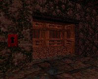 Fig 1. Insert the key hole sprite. |
1. First create your door. I'm using the ceiling to floor door (door1.map). We will use a red key to open this door. It is best to have a lock for the key on each side of the door. One on the side that the Single and Muli-Player modes will need, and the other for Wangbang (DeathMatch) mode if you have a start position somewhere on that side. Ok, in 3D mode (numeric pad Enter) place the cursor on the wall you want the lock to be at and hit "S". With the cursor still on the sprite press "V" twice and then "G" enter the value 1846 and hit Enter. Don't worry about the color yet. Go to 2D mode (numeric pad Enter) and place the cursor on the sprite you just created. Set the LowTag (Alt-T) to 29 and the HiTag (Alt-H) to 8 (red). Now, when you go back to 3D mode the sprite should be red. Do the same on the other side of the door.
2. Referring to the SPRITAGS.TXT file go to Hitag 29 (SECT_LOCK_DOOR). This is where you will find the following Keycards and Master Key colors.
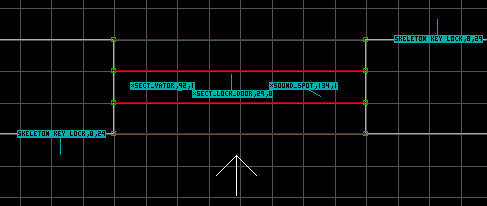 Fig 2. Insert the ST1 sprite. |
3. In 2D mode insert a ST1 sprite "S" (picnum 2307) in the door sector. Place the cursor on the new sprite and give it a HiTag of 29 (SECT_LOCK_DOOR) and a LowTag of 8 (red master key). Don't forget to put the red key (picnum 1777) somewhere in your map.
This is the basic tutorial to teach you how to link a switch to a door. So, when you hit a switch it will open a door. To view this map in Shadow Warrior download door4.zip
1. Create your door. We will use the door that we created in door1.map (Ceiling to Floor Door). You will recall our match tag for this door was 1.
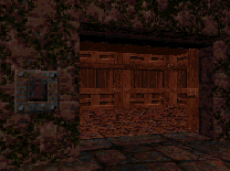 Fig 1. Inserting a switch sprite. |
2. Go to 3D mode (numeric pad Enter key toggles) and point the mouse cursor on the wall where you want the switch. Press "S" to insert the sprite. If the sprite for the switch you want to use did not appear point at the sprite and press "V" twice. The sprites for the switches are tiles (picnums) 551-584. Press "G" and enter 568 for our switch and press Enter to go to this sprite tile (picnum). Now press Enter and the sprite appears on the wall. You can click and hold on the sprite with the left mouse button and use the PgUp and PgDn keys to position the sprite's height on the wall. Release the mouse button when you are done. Since we assigned BOOL1 = 1 to our SECT_VATOR when we created our door in door1.map we must use the second switch tile (picnum) for the switch (trust me).
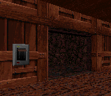 Fig 2. Insert another switch sprite. |
3. We need to put a switch on the other side of the door so it can be opened from both sides. Insert the switch the same way it was done in step 2 above. For the sake of variety I put a different switch (picnum 574) on this side of the door.
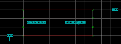 Fig 3. Insert two ST1 sprites. |
4. The ST1 sprite for the (SECT_VATOR Hitag 92) needs to have the TAG3 change from 0 to 1. To do this place the cursor on the SECT_VATOR sprite (2D mode), press ' and 3, enter a 1 and press Enter. Now the door will only operate by a switch with the same match tag (in our case 1). From the SPRITAGS.TXT file Section 3.3 give the switches a Lowtag of 206 and a Hitag of 1 (matching tag to SECT_VATOR Lowtag). To do this place the cursor on the sprite (2D mode) and press Alt-T enter 206. Now press Alt-H and enter 1. That's all there is to it.
This is the basic tutorial to teach you how to link a Gong to a door. So, when you shoot a gong it will open a door. To view this map in Shadow Warrior download doorgong.zip
1. Create your door. We will use the door that we created in door1.map (Ceiling to Floor Door). You will recall our match tag for this door was 1. I did change the speed of the door TAG4 to 80 (HiTag 92) and the sound TAG4 to 168 (HiTag 134).
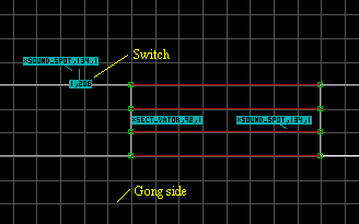 Fig 1. Inserting a switch sprite. |
2. We need to make a switch on the other side of the door so the player can open it to get back to the gong side of the doorway. Go to 3D mode (numeric pad Enter key toggles) and point the mouse cursor on the wall where you want the switch. Press "S" to insert the sprite. If the sprite for the switch you want to use did not appear point at the sprite and press "V" twice. The sprites for the switches are tiles (picnums) 551-584. Press "G" and enter 574 for our switch and press Enter to go to this sprite tile (picnum). Now press Enter and the sprite appears on the wall. You can click and hold on the sprite with the left mouse button and use the PgUp and PgDn keys to position the sprite's height on the wall. Release the mouse button when you are done. Since we assigned BOOL1 = 1 to our SECT_VATOR when we created our door in door1.map we must use the second switch tile (picnum) for the switch (trust me). Give the switch sprite a HiTag the same value as your matched LoTag for the door (1 in our case). Insert a ST1 sprite close to the switch and give it a HiTag of 134 (SOUND_SPOT) and a LoTag of the match door LoTag (1 in our case). Give the SOUND_SPOT a TAG4 value of 201 (switch sound). Note: you will hear this switch sound when you shoot the gong. So, you may opt not to put in this SOUND_SPOT for the switch.
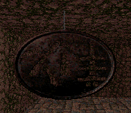 Fig 2. Inserting the gong sprites. |
3. We need to put two gong sprites (picnum 273) back to back. Give them a LoTag of 257 (TAG_SPRITE_HIT_MATCH section 3.2 of SPRITAGS.TXT) and point the angles in the opposite direction of each other (in our case one point west and the other pointing east). Give them both a LoTag of 2 (or your next match tag value). Give one a flag value of 151 (B, R, 1, H), and the other a flag value of 155 (B, F, R, 1, H). If your flag value is too high hit H again. Give each of the TAG_SPRITE_HIT_MATCH (gong) sprites the following TAGS:
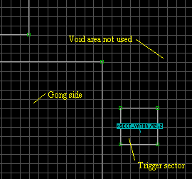 Fig 3. Creating a trigger sector. |
4. Ok, let's tie everything together. Make a small sector outside the play area (a place the player can not get to). Insert a ST1 sprite into this sector and give it a HiTag of 92 (SECT_VATOR) and a LoTag of 2 (the match tag of the gong). This sector will be treated as a ceiling to floor door so you need to flip the ST1 sprite. Place the cursor on this ST1 sprite and press F twice. No sound is given to this trigger sector. Give the following values to this ST1 sprite.
We needed to put in the trigger sector because of the sound match tags. We do not want to hear the sound of the gong when the switch is thrown, but rather the door sound. This is why the gong sound has a different match tag than our door.
This is a tutorial to teach you how to create a basic water pool. You can not dive down below it's surface, but you can sink a little in the water. To view this map in Shadow Warrior download water1.zip
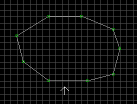 Fig 1. Inserting the water sector. |
1. Go to your room (sector) and insert your sector you want for the water. Do this in 2D mode (numeric pad Enter) by placing the cursor on a starting position and hitting the Space Bar. Move the cursor to the second postion and hit the Space Bar again. Keep doing this until you have connected back up with the starting position. Your line will be white. The shape of the water sector is up to you. It can be a square, rectangle or whatever. The more complicated you make it the better it looks, but the harder the work becomes when making diving sectors too. This is because the below water sector must have the EXACT same shape to it as the above water (this one) sector.
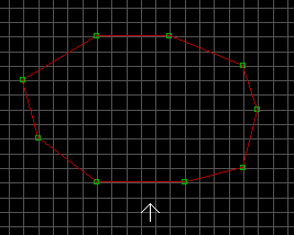 Fig 2. Creating the water sector. |
2. Still in 2D mode place the cursor inside of the to be water sector and press Alt-S. The white lines have now turned red.
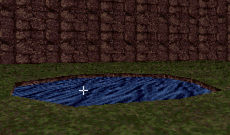 Fig 3. 3D mode of water sector. |
3. Go to 3D mode (numeric pad Enter) and place the cursor where you believe the water sector is and press PgDn twice. If you missed it press PgUp to undo your mistake and redue it in your to be water sector. Now, with the cursor still on the to be water sector press "V" twice then "G" and Enter 780 for the water tile to appear in your water sector floor.
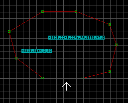 Fig 4. Inserting ST1 sprites. |
4. In 2D mode, insert two ST1 sprites (picnum 2307) in the water sector by pressing the "S" key. Give one ST1 sprite a HiTag (Alt-H) of 47 (SECT_DONT_COPY_PALETTE) and the other a LowTag (Alt-T) of 30 for the SECT_SINK sprite. The 30 is the depth Lo Wang will sink in the water.
This is a tutorial to teach you how to create a diving water pool. You are able to dive down below it's surface. To view this map in Shadow Warrior download water2.zip
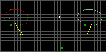 Fig 1. 2D mode view of both water sectors. |
1. Create a surface water pool as discribed in the Basic Water Pool tutorial. In 2D mode (numeric pad Enter), create the EXACT same shape and size sector as your surface water pool off to one side of your map using the Space Bar to create it. This newly created sector will be the underwater section of the water. For convenience sake let's call the surface water pool sector A and the underwater pool sector B.
2. It is very important to have standard practices when creating maps. Although, it is not required (in this case) to have the CEILING (water tile) Z-coordinates in sector B the same as the FLOOR (water tile) Z-coordinates in sector A it is a very good habit to have. However, if you are planning to have a Room Over Room (see through the surface of the water) situation here it you MUST have them the same (actually overlapping a bit). To find out the Z-coordinates of a sector go to 2D mode (numeric pad Enter) and place the cursor inside the sector. Press the TAB key and you can read the Z-coordinates under the FLOORS or CEILINGS columns. In my WATER2.MAP the Z-coordinate for sector A floor is 10240 and the Z-coordinate for sector B ceiling is 10240.
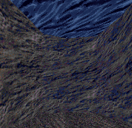 Fig 2. Underwater sector 3D mode view. |
3. Inside sector B (underwater sector), go to 3D mode (numeric pad Enter) and move the height of the ceiling to match the height of the floor in sector A. You will have to go back and forth between 2D and 3D modes to check the Z-corrdinates. Of course, you will have to lower the floor of sector B if the ceiling has to come down farther than it. Ok, now lower the floor of sector B to the depth you want. Insert the textures that you want to use and give all of the textures in your water sector a pallete value (Alt-P) of 8 while in 3D mode. It is a good ideal to give the same palette value to any items, plants, rocks, etc... that you place in this sector too.
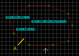 Fig 3. Inserting ST1 sprites in the surface water sector. |
4. In 2D mode, insert the two ST1 sprites (picnum 2307) in the water sector A as we did in the Basic Water Pool Tutorial. This time though assign the SECT_SINK a LowTag of 40 instead of 30. Now, insert a third ST1 sprites as shown. Give it a HiTag (Alt-H) value of 7 (SECT_DIVE_AREA) and a matching LoTag (Alt-T) of 1 (in our case for our first tag in this map).
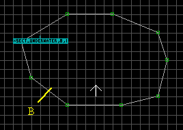 Fig 4. Inserting ST1 sprite in the underwater sector. |
5. In 2D mode, insert a ST1 sprite (picnum 2307) in the water sector B in the same grid position has we placed the SECT_DIVE_AREA sprite in sector A. Give it a HiTag (Alt-H) value of 8 (SECT_UNDERWATER) and a matching LoTag (Alt-T) of 1 (in our case).
This tutorial is designed to show how make an Exit switch in your maps. Also, you will learn how-to incorporate you maps into the Shadow Warrior game. There is no map to view in Shadow Warrior for this tutorial.
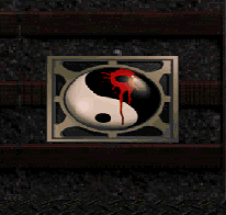 Fig 1. A 3D view of the Exit switch. |
1. To create the exit to your map all you need is the Exit switch, and the proper tags set to it. In my maps I have two Exit switches. One that can only be reached in Single and Multi-Player modes, and the other appears only in WangBang (DeathMatch) mode. You can also have an Exit switch to go to a secret map, should be harder to find. To make an Exit switch, go to 3D mode (numeric pad Enter) and place the cursor on the wall and press the S key. This inserts a sprite. We need picnum 2470 for the Exit switch. So, wich the cursor still on the sprite press V to view the picnums for your map and then V again to view all of the picnums. Press G and then BackSpace the number at the top. Warning, do not press G until your have press the V key the second time or your computer will lock up. Now enter 2470 and then Enter. The picture of the Exit switch will now be highlighted. Hit Enter again and your Exit switch is now on your wall.
2. If you need to move the Exit switch up or down on the wall you need to be in 3D mode. Place your cursor on the sprite and hold down the left mouse button. Now, use the PgUp and/or PgDn keys to position it. Release the mouse button when you are done. If you need to move the sprite to the right or left on the wall you need to be in 2D mode for this. Make sure your Grid square are small enough for you (G toggles you through the various sizes). Place the cursor on the sprite and hold down the left mouse button. Drag the sprite to where you want it and release the mouse button. Now, view it in 3D mode to see if you have it where you need it.
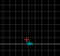 Fig 2. Tagging the Exit sprite. |
3. All Exit switches must have a LoTag of 116. To do this place the cursor on the sprite (in 2D mode) and press Alt-T. Now, enter the value 116 and press Enter. The HiTag is the map (or level) that you want exit to. If this is your first map then you would want it to go to the second map. So, you would enter 2 for the HiTag value. Generally, a HiTag of 1 will do for any map if it will only be played as a User Map. However, if you want to release your map(s) over the internet and/or have them incorporated into the Shadow Warrior game (not played as a User Map), then tag them to the next map level. Don't worry they still can be played as User Maps too.
4. When a map is played as a User Map and the player hits the Exit switch he is looped right back into the start of the map. It does not matter what the HiTag (within reason) of the Exit switch is. To have your map incorporated into the Shadow Warrior game, the official Shadow Warrior map name must be used. Warning, Never, (I repeat) Never, release a map with the official Shadow Warrior map name. If everyone did, think of the mass confusion there would be. Plus, your map would overwrite a map with the same name and someone with their map would overwrite yours. Let the people who will play the maps have control of how they will play your map. We will tell them how to do this in the text file that you zip up with your map (see paragraph 5 below).
| Map # | Map Title | Map Name |
| 01 | Seppuku Station | $bullet.map |
| 02 | Zilla Construction | $dozer.map |
| 03 | Master Leep's Temple | $shrine.map |
| 04 | Dark Woods of the Serpent | $woods.map |
| 05 | Rising Son | $whirl.map |
| 06 | Killing Fields | $tank.map |
| 07 | Hara-Kiri Harbor | $boat.map |
| 08 | Zilla's Villa | $garden.map |
| 09 | Monastery | $outpost.map |
| 10 | Raider of the Lost Wang | $hidtemp.map |
| 11 | Sumo Sky Palace | $plax1.map |
| 12 | Bath House | $bath.map |
| 13 | Unfriendly Skies | $airport.map |
| 14 | Crude Oil | $refiner.map |
| 15 | Coolie Mines | $newmine.map |
| 16 | Subpen 7 | $subbase.map |
| 17 | The Great Escape | $rock.map |
| 18 | Floating Fortress | $yamato.map |
| 19 | Water Torture | $seabase.map |
| 20 | Stone Rain | $volcano.map |
| 21 | Shanghai Shipwreck | $shore.map |
| 22 | Auto Maul | $auto.map |
5. Let's say that we have our first map and want it to be the first map in Shadow Warrior. The Exit switch HiTag will be 2 and the user must rename your mapname (ie joe1.map) to $bullet.map (the first Shadow Warrior map name). The $bullet.map is the first map in Shadow Warrior and we want to exit to the second map (HiTag value of 2). Now, all the user as to do is start Shadow Warrior (no User Map stuff needed) and your map is there. When they exit your map they go on to the Shadow Warrior second map. If you had a second map and it has been rename to $dozer.map then they would enter your second map and not the Shadow Warrior map. When the user is done playing your maps, they must rename your map(s) to anything other than the official Shadow Warrior map names. Remember, map 20 is the Exit map for the game, and maps 21 and 22 are used for the secrect levels. So, have the exits to the secret levels return back to the correct level in the game. Map 21 exits to map 11 and map 22 exits back to map 14. Which means, map 10 and map 13 can have a secrect exit. If you don't follow these simple guide lines you can easily cause improper loops in the game.
This is the basic tutorial to teach you how to create a Basic Elevator. To view this map in Shadow Warrior download elev1.zip
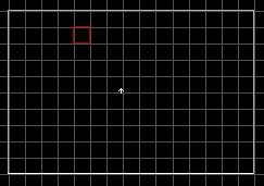 Fig 1. Room with peninsula sector. |
1. First create a room using the space bar in 2D mode. Go to 3D mode and raise the ceiling height kind of high for this demo. You can do this by placing the cursor on the ceiling and holding down the right mouse button and pressing the PgUp key. Next, go back to 2D mode and insert a sector inside the first sector that you created using the space bar. Place the mouse cursor inside this new sector and press Alt-S. You will notice that the lines have turned red (Fig 1) indicating a sector inside a sector (two way walls). This will be our elevator for this demo, and is treated as a door.
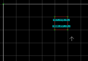 Fig 2. Insert ST1 sprites. |
2. Now insert a sprite in the second sector by pointing the mouse cursor in the door sector and hit "S". Go to 3D mode (numeric pad Enter) and the sprite will probably look like a gray wall tile (picnum). Place the cursor on it and press "V" twice. Now press "G" and enter 2307 and press Enter. This takes you to the ST1 sprite that we need. Now, press Enter again and we should be back in 3D mode with the ST1 sprite on the floor. Enter a second ST1 sprite which will be used for the sound in step 4.
3. Referring to the SPRITAGS.TXT file go to Hitag 92 (SECT_VATOR). Place the cursor on our first ST1 sprite in 2D mode and press Alt-H. Now enter 92 Enter. We need a low matching tag for our elevator, sounds, and anything else that we want connect to this door operation. If you don't know what your next tag number should be press F5 and it will tell you the next available tag number to use. In our case it will be 1. Press Alt-T and enter 1 Enter. There are TAG# and BOOL# numbers that need to address for our elevator to work at all. This you can see in the SPRITAGS.TXT mentioned above. To change the values of TAG# you press and hold the ' (under the ") key and the number you need to address. To change TAG3, press ' and 3 then enter the value and press Enter.
If you want the elevator to return after a period of time enter something like 35 to TAG9. Ok, now for the BOOL#. To enter a BOOL# you need to press ; and number. The number can only be a 1 or 0 nothing else.
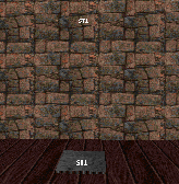 Fig 3. A 3D view. |
4. Insert another ST1 sprite next to the first one and give it a Hitag of 134 (sound spot) and the same Low tag of 1. Give TAG4 = 180 (the elevator sound). No BOOL# needs to be changed. Now, go back and raise the first sprite (Hitag of 92) to the height that you want the elevator to rise to. As with all door/elevator type sounds, you may have to play with the speed and/or height of the elevator so that when the sound stops so does the elevator.
This is the basic tutorial to teach you how to create a sector over another sector. It is not a room over room, but more like a two story house. You can not see the lower sector from the upper sector like you can in a room over room situation. To view this map in Shadow Warrior download secosec.zip
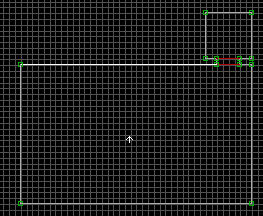 Fig 1. 2D mode view. |
1. First create two rooms with an archway. I made the smaller room to the north with a lower ceiling than the larger room (appearance sake). You must be a where of the floor and ceiling heights of the sectors that are to be over each other. In our case the larger room will be the one that is the lower sector. You can determine the z-coordinate height of the floor and ceiling by placing the mouse cursor in the sector and pressing the TAB key. My ceiling height in the lower sector is -57344. So, the floor of the upper sector floor must be -57345 or lower (negitive number so watch it). The lower the z-coordinate number the greater the height is. For example, -3 is lower than 3, but in Build the height of -3 is higher than the height of 3. Don't ask me why they did it this way it's just the direction the designer(s) picked.
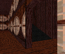 Fig 2. 3D mode view of ramp. |
2. Next, place in a hallway (ramp) that will lead to the upper level, and a small sector that will be at the top of the ramp. Raise the floor of this small sector to be higher than the ceiling of the lower (large) sector. Now, you can slope the ramp to meet the floor of the upper sector using the "[" and "]" and/or Shift-[ and Shift-] keys (3D mode). If your slope is not slanting in the desired direction, go to 2D mode and place the cursor (in this case) inside the ramp sector on the right side and press Alt-F. Go back to 3D mode and try it again. Of course, you can use steps or other means to get up to the upper level.
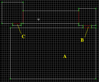 Fig 3. Create sector C and it's archway. |
3. It is best to overlap the upper and lower sectors. In other words, try not to
have all the lines (walls) from one level directly over all the lines (walls) of
the other. However, you can not under any conditions have any red lines
directly over/under any lines from the other level.
In Fig. 3, A is the lower sector (room), B is the lower archway, and C is the
upper archway. Notice that the red lines in the upper archway are not directly
over the lines of sector A (the lower sector).
 Fig 4. Colored sectors for this demo. |
4. For the purpose of a better understanding I colored the lines for the two
different levels. Green for the lower level A and Purple for the upper level D.
You will note that they do overlap to some degree. Line E is the two walls on
top of each other. This is shown with white lines. On line E you would not want
any red lines (two way walls).
If you want to insert any sectors or sprites into one of these sectors, do so in
the definite area. In this case that would be where the A and D letters are.
Then you can drag the object(s) into the area that you want to be at.
5. Again, this is a basic tutorial for creating a sector over a sector. There are many different ways to create this effect. You can create it where the floor or ceiling explodes leading the player to the new level height. You can create windows and doorways that can be used and seen from an outside area. Just make sure that the red lines are connected to only one level area line. I made a hotel type map for Duke Nukem call bab2.map. So, if you have Duke Nukem and it's Build engine check it out. It has windows, doorways and such leading in and out of the different level heights.
This tutorial is designed to show how create a mirror. To view this map in Shadow Warrior download mirror.zip
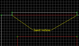 Fig 1. Inserting vertices on wall. |
1. To create a mirror go to an exterior (white line) wall that you want your mirror to be at and insert two vertices as shown in fig. 1. Go to 2D mode (numeric pad Enter) and place the cursor on the line and press the Insert key. Use the Space Bar to create the mirror sector. When you return to the starting postion the front line of the mirror sector will turn red.
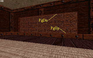 Fig 2. Lower ceiling and raise floor of the mirror sector. |
2. Go to 3D mode (numeric pad Enter) and raise the floor of the mirror sector for the bottom of your mirror. This is done by placing the cursor on the floor of the mirror sector and holding down the left mouse button and pressing the PgUp key. Now, lower the ceiling of the mirror sector to the desired height using the PgDn key.
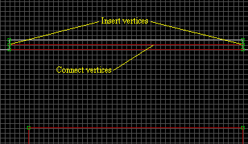 Fig 3a. Splitting the sector into two sectors. |
3a. As shown in fig. 3a, insert two more vertices between the others. If you need the grid squares smaller just press the G key to toggle the different sizes. Use the Space Bar to connect the two vertices, and the line (wall) will be red.
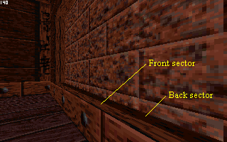 Fig 3b. Darken the Back sector floor. |
3b. In 3D mode, place the cursor on the Back sector and darken the floor (fig. 3b) using the numeric pad minus sign. This is so we can see where the Front and Back sectors are.
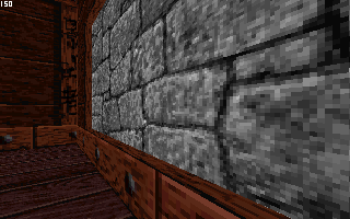 Fig 4a. Inserting a one sided wall. |
4a. In 3D mode, insert a one sided wall by placing the cursor on the Front sector floor and pressing the number 1 key. A texture will appear (usually the one shown in fig 4a).
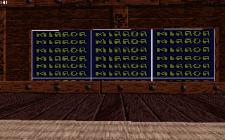 Fig 4b. Inserting the mirror texture. |
4b. Now, place your cursor on this gray texture and press V twice and go to picnum 340 and hit Enter. The mirror texture will now be on your one sided wall. One last thing is to go into 2D mode, and place your cursor on the front line of the Front sector and hit the B key. This will make the wall a blocking wall so the player can not jump up to the mirror.
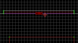 Fig 5. Letting Lo Wang speak to the mirror. |
5. If you want Lo Wang to say something when you press on the mirror then give the above mentioned blocking wall sound. To do this place the cursor just in front of the wall (in 2D mode) and press Alt-H and enter a HiTag of 900. Now press Alt-T and enter a LoTag of either 448, or 449. That's all there is to it. Just do not make any mirrors that can be seen by other mirrors, or you will have a mess on your hands.
This tutorial is designed to show how create a wall sprite, and a wall sprite that can not be blown up. To view this map in Shadow Warrior download wallsp.zip
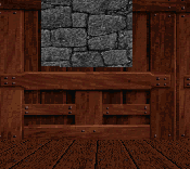 Fig 1. Inserting sprite on a wall. |
1. In 3D mode, place the cursor on the wall and press the S key. If you can not see the sprite save the map and reload the map and you should be able to see the sprite.
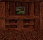 Fig 2. Change the sprite picnum to the one you need. |
2. Place the cursor on the sprite (3D mode) and press the V key twice. Choose the sprite that you want to use and press the Enter key. You can also load another level and go to the sprite that you want and press the TAB key to copy the sprite (while in 3D mode). Now, each time that you press the S key the copied sprite will appear. Pictures, signs, and such can not be blown up.
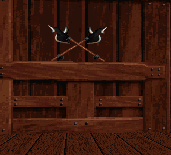 Fig 3. Insert a sprite that can be blown up. |
3. Sprites of swords, lights, and such can be blown up. In fig. 3 there are a set of axes on the wall and these can be blown up (by default).
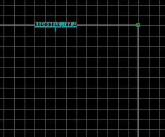 Fig 4. Override the break feature of a sprite. |
4. If for some reason you do not want a sprite to break up and disappear from your map give it a HiTag (Alt-H) of 132 (BREAKABLE_SPRITE). Give BOOL1 and BOOL2 a value of 1. Note: In 2D mode the sprite blue box will not read BREAKABLE until you give BOOL1 a value of 1. Also, if you want a sprite to disappear when shot (like a picture sprite) then give it a HiTag of 132 and a BOOL1 value of 1. BOOL2 must be left at zero. To enter a BOOL# value use the ; key and the BOOL#. For BOOL1 press both the ; key and 1.
This is the tutorial to teach you how to create a fog effect. To view this map in Shadow Warrior download fog.zip
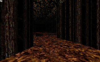 Fig 1. 3D view of area to have fog. |
1. Creating a fog effect is rather easily done. First, create the area that you want to have the fog effect in as you normally do.
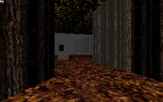 Fig 2. 3D view of area with some of the fog. |
2. With your area already shaded, just go into 3D mode and place the cursor on the texture needed to have the fog effect and press Alt-P. Now, give it a pallette value of 1 (one). For the best effect you need to give all of the walls, floors, and maybe the ceilings this pallette value of 1.
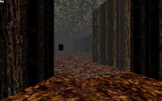 Fig 3. 3D view of the fog area. |
3. If you have any items in the fog area give them a pallette value of 1 too. Do not give any monsters this pallette value though. The darker that you shade a texture the more the fog effect will be shown. So, do your fog effects in darker areas.

This is the tutorial to teach you how to create Breaking Glass. To view this map in Shadow Warrior download glass.zip
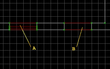 Fig 1. 2D view of area A and B. |
1. As shown in Fig 1. I created two sector areas, A and B. With area A we will use a masking wall effect for the glass, and with area B we will use a sprite for the glass. Let's do the sprite version first.
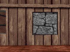 Fig 2. 3D view of area B with sprite added. |
2. Insert a sprite in the center of area B by pressing the S key while in 2D mode. Go to 3D mode and place the cursor on your sprite and press the R key. This keeps the sprite from following you as you move from side to side. You may need to change the angle of the sprite if your opening is not running in east/west directions as this tutorial is doing. In 3D mode, place the cursor on this sprite and press the V key twice, and go to picnum 282 for the glass texture and press the Enter key. Now, using the numeric arrow keys, resize the glass sprite until it fills your opening, and your done. Of course, this sprite has to be a blocking sprite (purple in color). To make it a blocking sprite, just press the B key with the cursor on it in 2D mode.
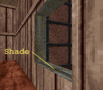 Fig 3. 3D view showing shaded area of area A. |
3. For area A I inserted 4 vertices and connected them using two lines. This gives us three sectors in area A. Shade the middle one as shown in Fig 3. In 3D mode, place the cursor in the sector in front of the shaded one and press the M key. A grayish wall should appear, or the last masking wall you made in your map. Place the cursor on this texture and press the V key twice. Again, use picnum 282 for the glass texture. You will have to check out both sides to see if the texture is sized correctly. If not, use the Shift + numeric pad arrow keys to correct this. Now, you lighten up the shaded area. I just do the shading to help see where the sectors are.
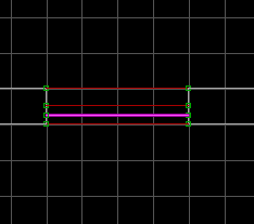 Fig 4. 3D view showing shaded area of area A. |
4. In 2D mode, place the cursor on the masking wall and press the B key to make the wall a blocking wall. In 3D mode, place the cursor on the glass texture and press the H for hitscan type wall.
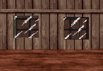 Fig 5. 3D view showing both glass windows. |
I prefer to use the masking wall version when I make windows.
This is the basic tutorial to teach you how to create a single sliding door that opens to the east (right) and closes to the west (left). To view this map in Shadow Warrior download door3.zip
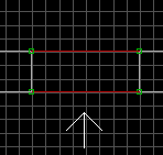 Fig 1. 2D view of archway. |
1. First create two rooms with an archway. Make the room heights at least 128 pixels height, and the archway 112 pixels high. When making the archway press "G" (2D mode) once from the default grid size. Make the archway 3 grid squares deep and 8 grid squares wide.
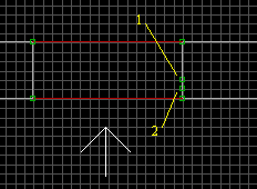 Fig 2. Insert two vertices. |
2. The actual sliding door is not a sector, but part of the solid (one sided) east wall in the archway. All we want to do is to insert vertices on this east wall in a precise order as to stretch out this wall. Press "G" (2D mode) again and insert vertice 1 and 2 as shown.
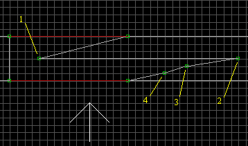 Fig 3. Insert next two vertices. |
3. Use the mouse to move vertice 1 to the left and up one. Move vertice 2 to the right and up two. Now insert vertices 3 and 4.
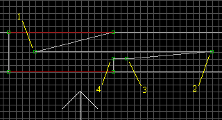 Fig 4. Positioning vertices. |
4. Move vertices 4 and 3 to the left as shown.
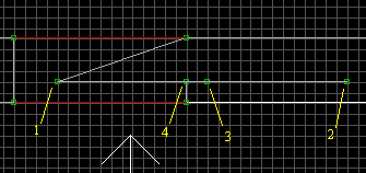 Fig 5. Positioning vertices. |
5. Move vertices 1 and 2 to the down as shown. This completes one side of our door. Now let's do the other side.
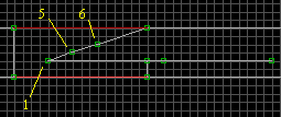 Fig 6. Insert two more vertices. |
6. Insert two new vertices 5 and 6.
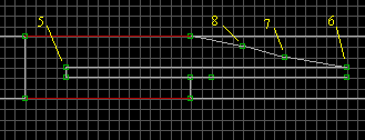 Fig 7. Insert two more vertices. |
7. As before, move vertices 5 and 6 to the places shown. Now, insert two new vertices 7 and 8 in the positions shown.
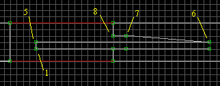 Fig 8. Position vertices. |
8. Position vertices 7 and 8 as shown.
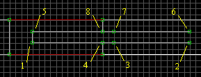 Fig 9. Position vertices. |
9. Move vertices 5 and 6 up to the positions shown.
 Fig 10. Tag the wall. |
10. This is important. You need to tag the line between vertices 1 and 5. Place
the cursor just to the left (in this case) of the line and press Alt-T. Enter
the value 221 and press Enter. Now, enter your tag you want for this door. You
can press F5 to see what your next unused tag is. In our case we will use 1. So,
press Alt-H and enter 1 then press enter. You will notice a small red box with
your values on the line. The tag value of 221 is for a door to open to the east
(right). A value of 220 will open a door to the west (left), 222 to open a door
to the north (up), and 223 to open a door to the south (down). Of course the
door would have to be designed in the correct direction for it to work.
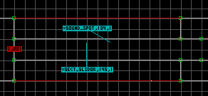 Fig 11. Insert ST1 sprites. |
11. Move vertices 1 and 5 to the west (left) wall of the archway sector. Remember, the door is not a sector it is the eastern wall stretched out into the archway sector. Do not place any sprites inside the door area. Any sprites that you want to control the door will be placed in the archway sector. Insert two ST1 sprites (picnum 2307) somewhere in the archway sector.
12. Referring to the SPRITAGS.TXT file go to Hitag 145 (SECT_SLIDOR). Place the cursor on a ST1 sprite in 2D mode and hit Alt-H. Now enter 145 Enter. We need a low matching tag for our door, sounds, and anything else that we want connect to this door operation. In our case it is still 1. Press Alt-T and enter 1 Enter. There are TAG# and BOOL# numbers that need to address for your door to work at all. This you can see in the SPRITAGS.TXT. To change the values of TAG# place the mouse cursor on the sprite (2D mode). Next, you press and hold the ' (under the ") key and the number you need to address. To change TAG3, press ' and 3 then enter the value and press Enter.
Ok, now for the BOOL#. To enter a BOOL# you need to press ; and number. The number can only be a 1 or 0 nothing else.
13. Go to the other ST1 sprite and give it a Hitag of 134 (sound spot) and the same Low tag of 1. Give TAG4 = 171 (the sound). No BOOL# need to be changed.
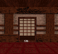 Fig 12. 3D view of door. |
14. All that you need to do now is just add the textures and shading (+ and - numeric pad keys) you want. Picnum 144 is a good one for this door. Use the numeric pad to stretch or shrink any tiles (2, 4, 6, and 8). To move (realign) a tile use the Shift key and (2, 4, 6, and 8).
This is the basic tutorial to teach you how create swinging doors connected to a fence. So, when you open the doors they will swing open. Though you do not need to make it this way. Rather, you can just have your swinging door(s) in a archway like the other doors. I just decided to do it this way. To view this map in Shadow Warrior download door5.zip
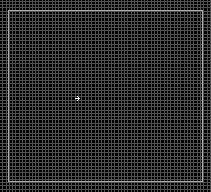 Fig 1. 2D mode of sector. |
1. Create a large sector (2D mode numeric Enter toggles). The doors will be 10 default grid squares each (20 for two doors). Make sure to have enough on each side of the doors for the fence. You can make everything smaller if you want. Make the height of this sector 240 pixels high. This is done in 3D mode by placing the cursor on the ceiling and holding the left mouse button down as you press PgUp. Go to 2D mode and hit the Tab key (with the cursor in the sector you are checking) and the height of the sector is displayed in the lower left of your screen. You can now add any textures you want for the walls, ceiling, and floor.
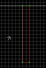 Fig 2. Peninsula sector. |
2. Insert two vertices on the north (top) wall two grid squares apart (2D mode). This is done by placing the cursor on the wall and press the Insert key. Now, place the cursor on one of the vertice you created and hit the Space Bar. Bring the cursor straight down the length you want this side of the fence to be and hit Space Bar. Move the cursor over to line up with the other vertice on the north wall and hit the Space Bar. Finially, move the cursor to the vertice on the north wall and hit the Space Bar. The line you just drew should have now turned red. If you need the wall longer or shorter in length just place the cursor on the lower vertices (one at a time), hold down the left mouse button, and move it to it's new location.
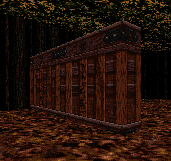 Fig 3. 3D mode of peninsula sector. |
3. Go to 3D mode (numeric pad Enter) and place the cursor on the floor where you think the new fence sector is. Press and hold the left mouse button and hit PgUp. If you did not get the fence sector hit PgDn, release the mouse button, and try again. Raise the sector so it's height is 100 pixels high (This is the height from the ceiling to the top of the fence). Change the fence texture to one you like. Now, create the second fence sector to the south of this one. I left 20 grid squares for the doors between the two fence sectors.
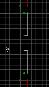 Fig 4. Creating island sectors. |
4. Go to 2D mode (numeric pad Enter) and create two rectangles (as shown) using the Space Bar. We do not want them connected to the fence sectors. These two rectangles will appear as impassable pillars in 3D mode.
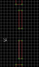 Fig 5. Creating island sectors. |
5. Place the cursor inside one of the white rectanglar box we created and hit Alt-S. The white lines now turn to red and we have created a sector inside a sector. Go ahead and do the same to the other one. Go to 3D mode and raise these two sectors as we did in step 3 above. Their height should be 112 pixels high.
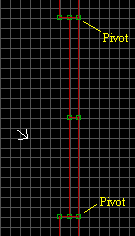 Fig 6. Positioning island sectors. |
6. Go to 2D mode and move the vertices of the two sectors (our doors) as shown. We do not want our doors to be connected to any other sectors. This is why we create them separate from the other sectors and then move the vertices over to the other sectors. The doors will open towards the east while rotating on the pivot vertices. The northern door will rotate counter clockwise and the southern door will rotate clockwise. The door sectors do not have to touch the other sectors as I have done. You can leave a tiny space between them, and is the best way to do it if the player(s) will be able to see the top of the doors. This is our plan so let's set it up with the ST1 sprites (picnum 2307).
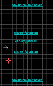 Fig 7. Adding ST1 sprites. |
7. Time to insert the ST1 sprites (picnum 2307). Go to 2D mode press "G" to go the smaller grid squares. Insert a ST1 sprite (hit "S")on each of the pivot vertices. Give these sprites a HiTag (Alt-H) of 144 (SECT_ROTATOR_PIVOT) and a LowTag (Alt-T) of 1 (our first match tag for this map). Insert a ST1 sprite inside each door sector. Give these sprites a HiTag of 143 (SECT_ROTATOR) and a LowTag of 1 (match tag). Insert a ST1 sprite somewhere by or on a door (for sound), and give it a HiTag of 134 (SOUND_SPOT) and a LowTag of 1 (our match tag for these doors).
8. Referring to the SPRITAGS.TXT file go to Hitag 143 (SECT_ROTATOR). Place the cursor on one of the ST1 sprite in 2D mode with this HiTag. There are TAG# and BOOL# numbers that need to address for your door to work at all. This you can see in the SPRITAGS.TXT. To change the values of TAG# place the mouse cursor on the sprite (2D mode). Next, you press and hold the ' (under the ") key and the number you need to address. To change TAG3, press ' and 3 then enter the value and press Enter.
Ok, now for the BOOL#. To enter a BOOL# you need to press ; and number. The number can only be a 1 or 0 nothing else.
No BOOL# needs to be changed for these doors.
 Fig 8. 3D view. |
9. All that you need to do now is just add the textures and shading (+ and - numeric pad keys) you want. Picnum 132 is a good one for this door. Use the numeric pad to stretch or shrink any tiles (2, 4, 6, and 8). To move (realign) a tile (picnum)use the Shift key and (2, 4, 6, and 8). If you want to copy a sprite, wall, ceiling, or floor texture just place the cursor on it in 3D mode and hit the TAB key. Now, when insert a new sprite, or point at the texture you want to change and hit Enter the copied sprite/texture will appear.
This is a tutorial to teach you how to create an underwater cave which will allow the player to swim to another room or area. This turorial is a continuation of the Basic Water Pool and Diving Water Pool tutorials. To view this map in Shadow Warrior download water3.zip
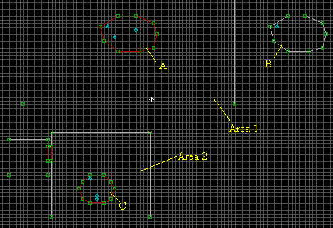 Fig 1. 2D mode view. |
1. Continuing on from the Diving Water Pool tutorial, create a second area (2) separate from the first area (1). Create a Surface Water Pool in area 2. Insert three ST1 sprites in sector C. Assign the same values to them as we did in the Diving Water Pool tutorial except give the SECT_DIVE_AREA (HiTag 7) sprite in sector C a new LowTag of 2 (in our case), or your next available tag on your map.
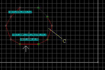 Fig 2. 2D mode view of sector C. |
2. Try and keep the floor height (Z-coordinate) of sector C the same (or at least close to) sector A. Just try to keep in mine, in a real world situation water seeks an equal level unless acted on by pressure or some other external force.
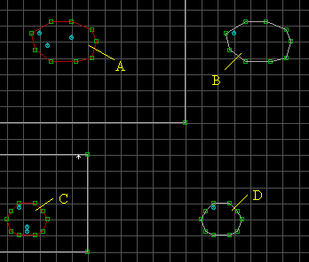 Fig 3. Create sector D. |
3. In 2D mode, create sector D with it being the exact same size and shape as sector C. Also, place sector D in the exact same position and distance from sector B that sector C is from sector A. Now, insert a ST1 sprite in sector D in the same position you place the SECT_DIVE_AREA sprite in sector C. Give this ST1 sprite a HiTag (Alt-H) of 8 (SECT_UNDERWATER) and a matching LowTag (Alt-T) the same value as the one in sector C (in our case 2).
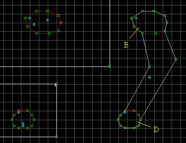 Fig 4. Connecting sectors B and D. |
4. Using the Space Bar create a connecting sector between sectors B and D. This will be the cave for the player to swim from one area to the other. Just go from vertice to vertice and when you come back to the starting positon the lines between the sectors should turn red (if you did it correctly). Now, in the cave sector insert a ST1 sprite and give it a HiTag of 8 (SECT_UNDERWATER). The LowTag stays at zero because this is just an underwater area and there is no way to suface in this area.
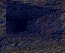 Fig 5. 3D mode view in sector B. |
5. In 3D mode (numeric pad Enter), make sure you lower the ceiling of the cave and change the ceiling texture to something other than a water texture. Also, change the palette (Alt-P) of the walls, ceiling, and floor to 9. Add any shading that you want (numeric pad - and + keys) and your done. In this picture, you are standing in sector B looking towards sector D.
This tutorial is designed to show how create one of three shooting traps. To view this map in Shadow Warrior download shoot.zip This tutorial was written by Starman, any questions you may have should be directed to him.
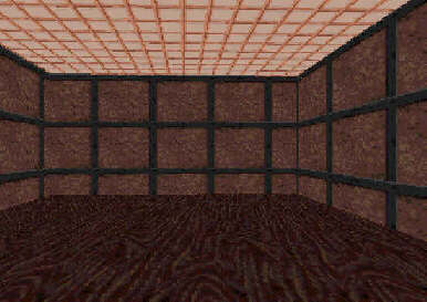 Fig 1. Create your Sector for your shooting trap. |
1. First create the sector where you want your shooter to go using the spacebar. The height of this sector whatever height suits you and apply some kind of texture to the walls and ceiling. The completed sector should look something like the one in Fig 1. Then create a child sector inside the main sector. To do this use the spacebar and then put the cursor inside this sector from 2D mode and hit ALT S. The walls of this sector will then turn red. This child sector will be your touchplate or trigger for the shooting trap.
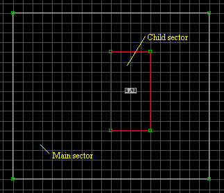 Fig 2. Tagging the trigger sector |
2. In 2D mode tag the trigger sector as follows. For a fireball trap Hi-Tag = 6 Lo-Tag = 43. For a Rocket trap Hi-Tag=7 Lo-Tag=43. For a Spear Trap Hi-Tag=8 Lo-Tag=43. Please note that in order to save space on the server I only showed the tags for a fireball trap in figure 2. To tag the sector...be in 2D mode and place the cursor inside the trigger sector. Then hit H for the Hi-tag....and T for the low tag. Do not use ALT-H or ALT -T as done to tag a sprite. The Hi-Tag is your next match tag. In 2D mode press F5 to determine what your next match tag is. I used 6, 7, and 8 for the match tags in this tutorial map. If you desire you can lower the trigger sector a few page downs as I have done, this depends on how hard you want the area to be. If you make the trigger sector hard to see, then the player will likely get injured or killed much quicker than if you make it easy to see. (Fig 2.)
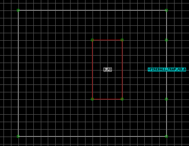 Fig 3. Inserting vertices for Trap. |
3. Inset Two vertices using the insert key from 2D mode as shown in Fig 3. This will allow you to place a different texture on the wall where you want your shooter to come from if you so desire. In my demo map I used the serpent head, picnum 159.....there are other ones you can use if you want to. You can also use a sprite such as picnum 209 instead of a wall texture.
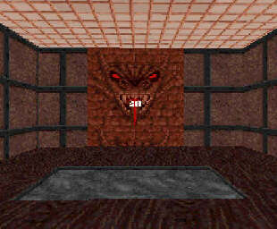 Fig 4. Adding The ST1 Sprite where the shooter will come from. |
4. All that is left now is to insert 1 ST1 sprite on the texture you used for your shooter (Fig 3). Please note that a different texture is NOT required. For the shooter to work all that is needed is the ST1 sprite and the trigger sector. I only inserted a different texture to add more realism. Usually this ST1 sprite will need to be placed up on the wall a bit. Also point the sprite in the direction you want the trap to travel using the < or > keys. The Tags for this sprite are as follows. Fireball Trap Hi-Tag=43 Lo-Tag=6. Bolt Trap Hi-Tag=44 Lo-Tag=7. Spear Trap Hi-Tag=63 Lo-Tag=8. Where the Lo-Tags here are your match tag(s) that you used in step 2 for the match Hi-Tag(s) in the sector(s). And that is all there is to it.
This tutorial is designed to show how create an auto turret. It is best that you have section 4 of the ADVANCED.TXT handy while going over this turtorial. To view this map in Shadow Warrior download turret.zip (Updated 24 March 1998).
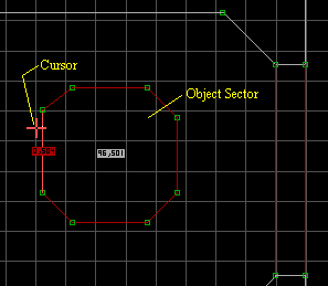 Fig 1. Main Auto Turret (object) sector. |
1. First, create the sector that you plan to place your turret sector in. Next, create the outer most part of the turret (object) sector. This I call the object sector, or main object sector. Before you create any sectors within the main object sector it is a good habit to tag it first. Our turret (in this case) will pivot around the center of this sector. Tag the sector object first by placing the cursor inside it (2D mode) and pressing T (sector LoTag). Enter the value of 501 (our first sector object). Next, press H (sector HiTag) and enter 96 for the auto turret value. Finally, we need to tag the wall loop (section 4.1.1) with a LoTag of 504. Make sure that you place the cursor on the outside of the wall (see fig. 1). Note: any wall of the object sector will work, but tag only one wall.
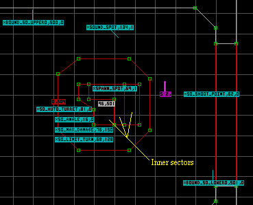 Fig 2. 2D mode view. |
2. Once you have created the inner sectors for appearance (as shown in figs. 2 and 3) we can insert the gun barrel sprite (purple sprite). Note: make sure that you give the top (floor textures) of the turret a Flag value of 48 (4a for sloped). This is done by placing the cursor on them and pressing the E and R keys in 3D mode. Use picnum 764 and a Flag value of 141 for the gun barrel sprite. We need to insert four key ST1 sprites into the main turret object sector (the one that we tagged in step 1 above), not in the inner sectors. If you place these ST1 sprites in a non-tagged inner sector the sprite(s) will have no effect. Give the first ST1 spirte a HiTag of 81 (SO_AUTO_TURRET) and point the angle towards the front of the sector object (towards the right, or east in out case). Give the second ST1 sprite a HiTag of 16 (SO_ANGLE) and point the angle towards the front. The third ST1 sprite is given a HiTag of 76 (SO_MAX_DAMAGE) and a LoTag value for it's health (I gave it 150). Also, set TAG3 and TAG5 to 0 (zero), and point the angle towards the front. This sprite is for the amount of damage it can take (150 in our case) from an exploding type weapon before it breaks down. We will add a spawn sprite shortly to show that it is broken. The forth ST1 sprite HiTag 68 (SO_LIMIT_TURN) tells the sector object how far it is aloud to pivot around the tagged center of the main object sector. The is controled by the LoTag which I gave a value of 128. Which is 22.5 degrees in either direction from the center point for a total of 45 degrees total. As with the others, point the angle towards the front.
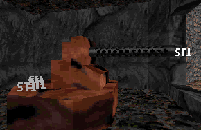 Fig 3. 3D mode view. |
3. Insert a ST1 sprite at the very end of the gun barrel sprite, and give it a HiTag of 62 (SHOOT_POINT). Point the angle towards the front, and give TAG3, TAG5, TAG6, and BOOL1 a value of 0 (zero). TAG3 = 0 is for a tank shell, and can be given another value if you want to (see HiTag 62 in the SPRITAGS.TXT file). Place a ST1 sprite where you want the smoke to appear on the turret when it becomes broken. It must be within the main object sector, but can be in one of the inner sectors. Give it a HiTag of 69 (SPAWN_SPOT) and a LoTag of your next available match tag value (press F5 in 2D mode for this info). I used 1 in our case cause it is the first match tag value for this map. Give TAG3 and TAG6 a value of 3 (for smoke to appear), and you can point the angle towards the front. As shown in fig. 2a, Insert another ST1 sprite for a SOUND_SPOT (HiTag 134) somewhere close to the turret object sector. Give it the same match tag that you gave to the SPAWN_SPOT sprite (1 in our case). Now, give TAG4 a value of 276 (hissing sound) and BOOL2 a value of 1.
4. Finally, we need to insert two more ST1 sprites to create what is known as the Bounding Box (section 4.1.2 of the ADVANCED.TXT). This is an "imaginary rectangle" that must be large enough to contain the entire outer wall loop plus the sprites that will move with the sector object (the gun barrel and SHOOT_POINT sprites in our case). The first ST1 sprite is given a HiTag of 500 (BOUND_SO_UPPER) since it is our first sector object on the map. It is placed to the upper left of the sector object. The second ST1 sprite is given a HiTag of 501 (BOUND_SO_LOWER). You will note that this is and MUST be the same value of the LoTag given to the main object sector in step 1 above. This sprite is placed to the lower right of the sector object. Remember, this imaginary rectangle must contain the entire outer wall loop PLUS the gun barrel and SHOOT_POINT sprites.
This tutorial is designed to show how create an operational turret. It is best that you have section 4 of the ADVANCED.TXT handy while going over this turtorial. To view this map in Shadow Warrior download turop.zip.
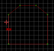 Fig 1. Turret object sector. |
1. First, create the sector that you plan to place your turret sector in. Next, create the outer most part of the turret (object) sector using the space bar. Place the cursor inside this sector and press the Alt-S keys and the lines will turn red. This I call the object sector. Before you create any sectors within the object sector it is a good habit to tag one of the walls of this wall loop first (section 4.1.1). with a LoTag of 504. Make sure that you place the cursor on the outside of the wall (see fig. 1). Note: any wall of the main object sector will work, but tag only one wall. Go into 3D mode and raise this sector up 8 PgUps.
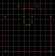 Fig 2. Creating the gun base sector. |
2. In 2D mode, create the gun base sector using the space bar then the Alt-S keys(fig. 2). The front of the turret will face to the north (towards the top of the picture).
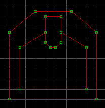 Fig 3. Player area. |
3. Using the space bar create the sector the player will operate the turret from. When you have connect the last vertice the lines should turn red. In 3D mode, raise the gun base sector 2 PgUps, and lower the player area 8 PgDns (the original ground level). You can now change the textures to what you want. I used picnums 754 for the outside, 8 for the inside, 4970 for the control panels, 2793 for the back side of the gun base, 398 for the front side of the gun base, and 2791 for the back of the gun base. For the top (floor textures) of the turret I used 754 for the outer sector, 2790 for the top of the gun base, and 4733 for the floor player area. All of these floor textures MUST be flagged in 3D mode using the R key and the E key if desired (I use it). Also, the gun base floor texture may have to be flipped using the F key. If you do not use the R key on the floor textures of the turret, the floor textures will not move with the turret.
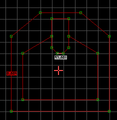 Fig 4. Tagging the player sector. |
4. You need to tag the player sector. In 2D mode place the cursor inside the player sector (fig. 4) and press H and enter 97. Now, press T and enter 501 (for our first sector object).
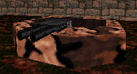 Fig 5. Insert the gun barrel sprites. |
5. In 2D mode, insert two barrel sprites and change the angle to face to the right. Go into 3D mode and place the cursor on one (picnum 764) and press B, R, and H. This will set the Flags to 11 for the sprite. Now, do the same to the other barrel sprite.
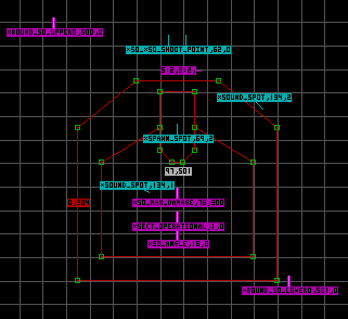 Fig 6. Inserting ST1 sprites. |
6. Insert a ST1 sprite at the very end of each gun barrel sprite, and give them a HiTag of 62 (SHOOT_POINT). Point the angle towards the front, and give TAG5, TAG6, and BOOL1 a value of 0 (zero). TAG3 = 1 is for a machine gun, and can be given another value if you want to (see HiTag 62 in the SPRITAGS.TXT file). We need to insert four key ST1 sprites into the player object sector (the one that we tagged in step 4 above). If you place these ST1 sprites in a non-tagged sector the sprite(s) will have no effect. Give the first ST1 spirte a HiTag of 1 (SECT_OPERATIONAL). Give the second ST1 sprite a HiTag of 16 (SO_ANGLE) and point the angle towards the front. The third ST1 sprite is given a HiTag of 76 (SO_MAX_DAMAGE) and a LoTag value for it's health (I gave it 200). Also, set TAG3 and TAG5 to 0 (zero), and point the angle towards the front. This sprite is for the amount of damage it can take (200 in our case) from an exploding type weapon before it breaks down. We will add a spawn sprite shortly to show that it is broken. The forth ST1 sprite has a HiTag of 134 (SOUND_SPOT) and your next match tag value 1 for our map (first match tag). Give TAG4 = 152, TAG5 = 154, and BOOL2 = 1 (very important). The next ST1 sprite gets a HiTag of 69 (SPAWN_SPOT) and a LoTag of 2 (next match tag for map). Set TAG3 and TAG6 to 3 for smoke to appear on the turret when it becomes broken.
Ok, we need to insert two more ST1 sprites to create what is known as the Bounding Box (section 4.1.2 of the ADVANCED.TXT). This is an "imaginary rectangle" that must be large enough to contain the entire outer wall loop plus the sprites that will move with the sector object (the gun barrels and SHOOT_POINT sprites in our case). The first ST1 sprite is given a HiTag of 500 (BOUND_SO_UPPER) since it is our first sector object on the map. It is placed to the upper left of the sector object. The second ST1 sprite is given a HiTag of 501 (BOUND_SO_LOWER). You will note that this is and MUST be the same value of the LoTag given to the turret object sector in step 4 above. This sprite is placed to the lower right of the sector object. Remember, this imaginary rectangle must contain the entire outer wall loop PLUS the gun barrels and SHOOT_POINT sprites. Insert another ST1 sprite for a SOUND_SPOT (HiTag 134) somewhere within the Bounding Box (I placed it in the upper right). Give it the same match tag that you gave to the SPAWN_SPOT sprite (2 in our case). Now, give TAG4 a value of 276 (hissing sound) and BOOL2 a value of 1 (important).
This is the basic tutorial to teach you how to create an Elevator which takes the player from a lower room to an upper room. To view this map in Shadow Warrior download elev2.zip
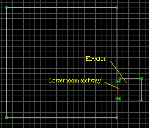 Fig 1. Lower room and elevator. |
1. First create a room using the space bar in 2D mode. Go to 3D mode and raise the ceiling height. You can do this by placing the cursor on the ceiling and holding down the right mouse button and pressing the PgUp key. Next, go back to 2D mode and insert an archway sector using the space bar. Now create the elevator shaft which is basically a small room (see fig 1). The elevator is treated as a floor to ceiling door that can crush players. For now, just make the height of the elevator ceiling a little higher than the archway ceiling.
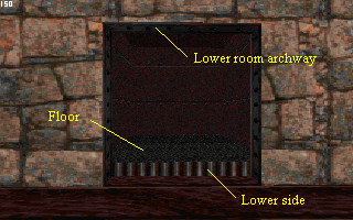 Fig 2. 3D veiw of lower room and elevator. |
2. Raise the floor of the elevator so you can see the lower side of it (the side facing the lower room). This is the only side of the elevator that will be seen as the elevator goes up. So, change the texture to one that you want to use (I used picnum 266). Now, lower the floor of the elevator back down equal to the lower room (and archway) floor heights. For this tutorial I made the floor of the upper room a little higher than the ceiling of the lower room. Just in case you wanted to play around with another version of a sector over sector.
3. Ok, raise the ceiling height of the elevator higher than the height of the lower room ceiling. This is done in 3D mode by placing the mouse cursor on the ceiling and holding down the left mouse button and hitting the PgUp key. If you released the mouse button and need to raise or lower the ceiling some more but can't see the ceiling anymore to place the cursor on it, press the Caps Locks key twice and then the A key to raise yourself up to it (while your inside the elevator shaft). When you are done press the Caps Lock key again and you will fall back down to the floor.
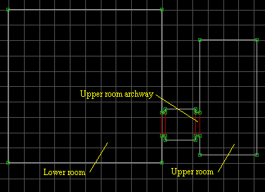 Fig 3. Creating the upper room area. |
4. Create the upper room archway in the position shown in fig 3. Go into 3D mode and raise the floor of this archway to be higher than the ceiling height of the lower room. Make sure that you have the upper room archway ceiling lower than the elevator shaft ceiling. So, you will have move all the ceilings up and down accordingly. Finally, create the upper room itself making sure that you raise the ceiling of the upper room higher than the ceiling of the upper room archway (for appearance sake).
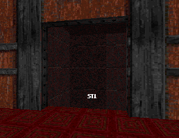 Fig 4. 3D veiw from the upper room. |
5. Since we want the elevator to come up to the upper room level, we want it to stop flush with the upper room and upper archway floor. The easiest way to do this is to insert the ST1 sprite (picnum 2307) on the upper level first. Now, drag the ST1 sprite into the elevator sector. As you may recall, a floor to ceiling door will rise to the bottom of the ST1 sprite, and doing it this way eliminates the guess work where the bottom of the ST1 sprite is.
6. Referring to the SPRITAGS.TXT file go to Hitag 92 (SECT_VATOR). Place the cursor on the ST1 sprite (in 2D mode) and press Alt-H. Now enter 92 Enter. We need a low matching tag for our elevator, sounds, and anything else that we want connected to this elevator operation. If you don't know what your next tag number should be press F5 and it will tell you the next available tag number to use. In our case it will be 1. Press Alt-T and enter 1 Enter. There are TAG# and BOOL# numbers that need to address for our elevator to work at all. This you can see in the SPRITAGS.TXT mentioned above. To change the values of TAG# you press and hold the ' (under the ") key and the number you need to address. To change TAG3, press ' and 3 then enter the value and press Enter.
If you want the elevator to return after a period of time enter something like 35 to TAG9. Ok, now for the BOOL#. To enter a BOOL# you need to press ; and number. The number can only be a 1 or 0 nothing else.
BOOL1 = 0 is for the position of the elevator is in Build. If you set BOOL1 = 1 then the elevator will be where our ST1 sprite is. BOOL2 = 0 must be set this way in this situation, or the elevator will never go back down while the player is standing on it. BOOL7 = 1 means that we do not want the monsters to activate the elevator.
7. Insert another ST1 sprite next to the first one (in the elevator shaft) and give it a HiTag of 134 (SOUND_SPOT) and the same Low tag of 1. Give TAG4 = 180 (the elevator sound). No BOOL# needs to be changed. As with all door/elevator type sounds, you may have to play with the speed (TAG4) of the ST1 sprite with the HiTag of 92 so that when the sound stops so does the elevator.
This tutorial is designed to show how create a teleporter. To view this map in Shadow Warrior download telep.zip
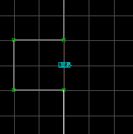 Fig 1a. 2D view of teleport chamber. |
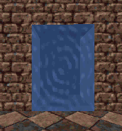 Fig 1b. 3D view of teleport chamber. |
1. The norm in the Shadow Warrior game is a teleporter chamber to teleport the player from one place to another. These chambers are usually found in WangBang (DeathMatch) mode. The chamber lets the player know that they are about to be teleported. So, it is designed for appearance and nothing else. To make a chamber just set your grid to the largest setting and insert two vertices on the exterior wall. Now, make the square chamber one grid sqaure in size. Give it a height of 112. For the ceiling, floor, and walls use picnum 310. Shade the ceiling, floor, and the back wall. Insert a sprite at the front center of the chamber, and give it a picnum of 890 with the angle pointing out. Give the sprite the Flag value of 212. This is done by placing the cursor on the sprite (in 3D mode) and pressing the T, R, and T keys. Now, stretch the sprite to fit in the opening. If you want to change the color of the chamber use the Alt-P option to change the palette value (including the sprite).
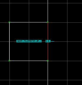 Fig . Insert the ST1 sprite. |
2. You need to have two ST1 WARP_TELEPORTER (HiTag 84) sprites for a teleporter to work. One in the sector the player is teleporting from, and the other in the sector the player is teleporting to. Both will have the same Match tag value (LoTag). Both sectors should be the same size (there is some leeway here though). Make sure that you have the sprite angle pointing towards the front of the chamber, or the direction you want the player facing when they teleport into this sector.
A Two-Way Teleporter allows the player to teleport back and forth between both of the teleporting sectors (chambers). Set the TAG# values for the ST1 (HiTag 84) as indicated below.
This tutorial is designed to show how create a wall with a crack in it that can be blown. The wall blows open when shot by an explosive weapon to reveal an area behind it. To view this map in Shadow Warrior download blow1.zip
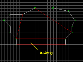 Fig 1a. Archway with hidden area. |
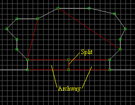 Fig 1b. Archway split into two sectors. |
1. First, create an archway and the hidden area that you want to be found when the wall (archway) is blown up (fig. 1). Raise the floor of the archway a little for appearance. Now, split the archway sector by inserting two vertices and connecting them with a line. What this does, is it makes the split wall the first wall of each of the archway sectors. Use the [ and ] keys to slope the floor and ceiling of the archway sectors. Generally, make the opening of the archway sector wider on the side that has the first wall on it. If you run your map and the opening is not close all the way. This may be the problem. To make a wall the first wall of a sector. Go to 2D mode, and place the cursor on the inside of that wall and press Alt-F. If desired, slope the floor and ceiling of the hidden area too.
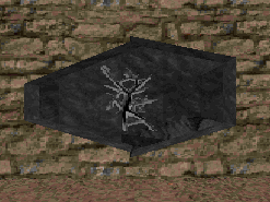 Fig 2. 3D view with the crack sprite. |
2. With the wall above the archway in the main area, I set the orientation of the wall texture by pressing the O key (3D mode). Insert the crack sprite onto the archway wall by placing the cursor on the wall above the archway and pressing the S key. Change the sprite to picnum 80 (see section 3.2 of the SPRITAGS.TXT). Use the PgDn key to position the crack sprite in the archway opening. The shape ot the opening in Build is what will appear when the wall (archway) is blown during game play. Give the crack sprite a LoTag of 257 and a HiTag of 1 or your next available match tag value. Note, that the match tag is the HiTag value for the crack sprite. Give TAG3=32, TAG7=0, and TAG8=0 values to the crack sprite.
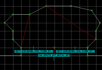 Fig 3. Inserting ST1 sprites into the archway sectors. |
3. Insert a ST1 sprite in each of the archway sectors. Give them a HiTag of 57 (SECT_EXPLODING_CEIL_FLOOR), and a LoTag the same as your match tag in step 2. These ST1 sprites are the ones that will bring the floor and ceiling of the archway sectors together at pre-map load. They are also the sprites that raise the floor and ceiling to the heights given to them in Build when the crack sprite is blown. That's it, you are now done with this effect. However, if you wish to have more explosions then go to step 4.
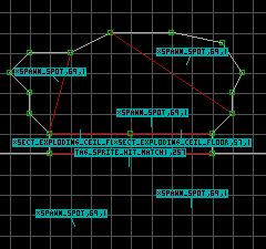 Fig 4. Inserting ST1 sprites for additional explosions. |
4. I inserted five ST1 sprites that will be used for additional explosions when the crack is blown. Give them a HiTag of 69 (SPAWN_SPOT), and LoTag of your match tag (1 in our case). Use the PgUp key to place them at the height you want them to explode at (3d mode).
5. The TAG5 values should not be the same. I used 2, 3, 5, 7, and 8. Just play with these values until you get the effect that you want. Also, the color of the ST1 sprite does not have to be red like I used in my blow1.map. I just do that so I know that these ST1 sprites are for explosions when I'm creating my maps in Build.
This tutorial is designed to show how create a wall that can be blown, and the floor in front of the wall. It is a continuation from the Blow 1 tutorial. The wall blows open when shot by an explosive weapon to reveal an area behind it. To view this map in Shadow Warrior download blow2.zip
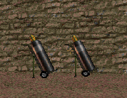 Fig 1. Play view of the wall to be blown. |
1. This is a continuation of the Blow 1 tutorial. The difference with this tutorial is to show you how to use the SECT_COPY_DEST and SECT_COPY_SOURCE ST1 sprites. These are very powerful (you can do all kinds of neat tricks with them), and once you master them your maps will become far more enjoyable to play. We will leave all of the sprites that we used it the Blow 1 tutorial except the crack sprite. As shown in Fig 1. we will use two cylinder tanks (picnum 648) to give the illusion for the cause of the explosion. We will use the picnum 3123 for our explosion sprite, and it will be tagged not to be seen during game play.
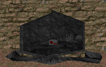 Fig 2. Play view after the explosion. |
2. Fig 2. shows you what it will look like once the explosion has occurred. We will create the blown out floor in front of the wall. So, the player is given the illusion that the cylinders blow part of the floor away.
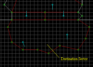 Fig 3. Creating a Destination sector. |
3. First, create the sector in front of the wall to be blown up. Start at one of the vertices and use the Spacebar to make the sector until you connect to the other vertice of the wall. If you need to add more vertices, just place the cursor on the line and press the Insert key.
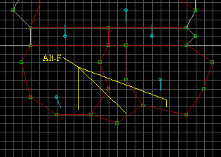 Fig 4. Creating the Destination sectors. |
4. Using the Spacebar, create two more sectors within the one you just created in step 3. Since we want the blown out floor to be sloped for a better effect, we must use the Alt-F option to indicate which wall(s) we want to be the first wall of each sector. Place the cursor inside the southern (lower) end of the sector near the wall that you want to be the first wall and press Alt-F. Do this to the other two sectors too. To test it, go to 3D mode and place the cursor inside one of these sectors, and press the [ or ] key once. It will be hard to determine where the sector is. Make sure that you use the ] or [ key to place the sector back to its' flat position. This Alt-F step must be done before going on to step 5.
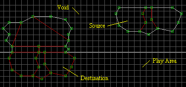 Fig 5. Creating the Source sectors. |
5. Ok, you have your destination sectors the size and shape that you want. You also have the first wall indicated for each of the destination sectors. Save your map before you try to Copy and Paste. Now go ahead and Copy the destination sectors. Paste them somewhere in the void space (non player area). These newly copied sectors will be known as the Source sectors. If you have any sprites within the source sectors delete them out at this time. In the source sector, leave the textures on the North wall be. You can change the remaining wall textures. I used the same grayish texture as in the the blown out area. Slope the floors of the Source sectors as desired and change the floor textures too.
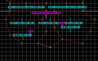 Fig 6. Inserting sprites into the Destination sectors. |
6. Since we used 1 for our Match tag in the Blow 1 tutorial we will continue using it here. In place of where the crack sprite was insert the picnum 3123 sprite. Make it a blocking sprite (B key), and a wall sprite (R key). Give it a LoTag of 257 (TAG_SPRITE_HIT_MATCH) and the matching tag (1 in our case). The following TAGs are used:
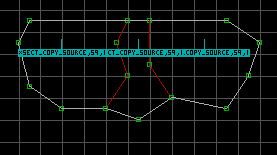 Fig 7. Inserting sprites into the Source sectors. |
7. Ok, insert a ST1 sprite in each of the Source sectors. Give them a HiTag of 59 (SECT_COPY_SOURCE), and a LoTag of 1 (our match tag). From left to right give them a TAG3 of 1, 2, and 3. So, when the wall is blown the source sector with the ST1 sprite TAG3 of 1 will be copied to the destination sector with the ST1 sprite TAG3 of 1, and so on.
This tutorial is designed to show how create a torch with a lighting effect. To view this map in Shadow Warrior download torch.zip This tutorial was written by Starman, any questions you may have should be directed to him.
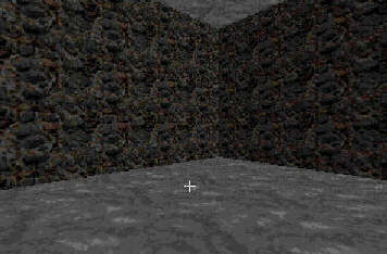 Fig 1. Shading the walls of the main sector. |
1. First create the sector where you want your torch to go using the spacebar. The height of this sector whatever height suits you and apply some kind of texture to the walls and ceiling. The completed sector should look something like the one in Fig 1. Notice how the walls are shaded differently? To create a realistic effect, correct shading is important. Use the numeric keypad - key (3D mode) to darken one of your walls, then hit Shift CTRL Enter. This should shade it for you correctly.
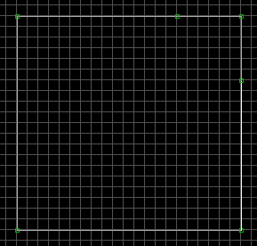 Fig 2. Insert vertices. |
2. In 2D mode, Insert 2 vertices as shown (Fig 2.) above in one corner of your sector using the Insert key.
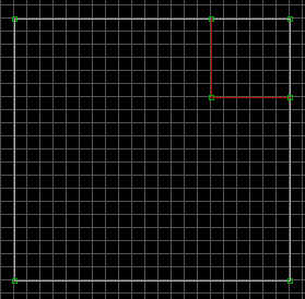 Fig 3. Creating another sector. |
3. Connect the two vertices using the spacebar. The lines will turn red as shown in Fig 3.
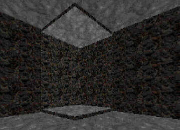 Fig 4. Darken the Back sector floor. |
4. In 3D mode raise the level of your split (child) sector a couple of page-ups. You can also lower the ceiling here if you desire. There are several different ways to do this.....I am just showing you one of the easiest. When completed the sector should look like the illustration above. Use the plus or minus keys on the numeric keypad to shade this split sector to be lighter than the walls of the main sector.
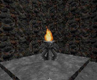 Fig 5. Inserting the torch sprite. |
5. Now we are ready to insert our torch sprite. Place the cursor on the spot where you want your sprite to go and hit the "S" key. Usually a gray texture will appear. Then hit the "V" key twice. Then hit the "G" key and type 430 and hit enter. There are other torch sprites available but picnum 430 is the one I used here.
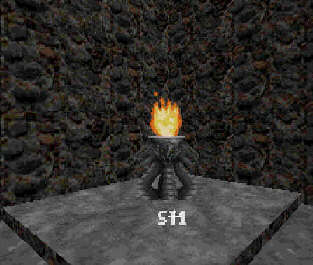 Fig 6. Inserting a ST1 sprite. |
6. Inserting the ST1 sprites and tagging them properly. I am going to assume here that you know what an ST1 sprite is. For those of you that don't it is picnum 2307. Insert an ST1 sprite at the base of the torch sprite and give it the following tags. Hi-tag should be 69 (SPAWN_SPOT), Low-tag should be your next match tag....hit F5 from 2D mode to see what your next match tag is. Tag 3 should be 12, Tag 4 should be 1536, Tag 5 should be 12. When you are done tagging this sprite from 2D mode it should look something like Fig 6. in 3D mode.
 Fig 7. Raising the ST1 sprite. |
7. Now we need to raise this sprite up to the level of the torch. Use the PgUp key to get this done. When finished it should look something like Fig 7.
 Fig 8. Tagging the torch and adding a ST1 sprite. |
8. Next place the cursor on the torch sprite itself and give it the following tags. Note: this can be done from either 3D or 2D mode. Hit Alt-H from 2D mode for Hi-Tag and Alt-T for Low-Tag. From 3D mode it is '1 for Hi-Tag and '2 for low tag and so on. The torch gets Hi-Tag which is your next match tag and a Low-Tag of 257 (TAG_SPRITE_HIT_MATCH). Tag 3 should be 32, Tag 4 should be 1536, Tag 5 should be 0, Tag 7 should be 3, And Tag 8 should be 2. Next we need to insert one more ST1 sprite at the base of our torch and give it the following tags. Hi-Tag should be 108, Low-Tag should be the same as the Hi-Tag we just gave our torch sprite. Tag 3 should be 2, Tag 4 should be 8, Tag 5 should be 20, Tag 7 should be 1, And Bool1 should be 1. The map should now look something like the Fig 8. in 3D mode.
9. Okay, we now need only one more sprite to complete our map. Insert one more ST1 sprite somewhere in our main sector and give it the following tags. Hi-Tag should be 109 (LIGHTING_DIFFUSE), Low-Tag should be the same as the Hi-Tag we gave our torch sprite, Tag 3 should be 2, Tag 4 can be either 2,4,or 6 depending on the speed and intensity of the effect you desire. Tag 5 should be 20 and you are done. Seems like alot to do to get the walls to flicker with your torch but the rewards in realism in your maps are well worth it.
This is the tutorial to teach you how to create a Spawning items. The bunny.map also has a trap shoot to shoot at flying bunnies. To view this map in Shadow Warrior download bunny.zip
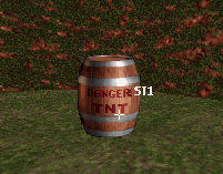 Fig 1. 3D view of barrel we want to spawn an item from. |
1. As shown in Fig 1. I use picnum 713 for the barrel that I want to explode and spawn a medical kit out. You will note that I place the ST1 sprite for the explosion to be about half way up the height of the barrel.
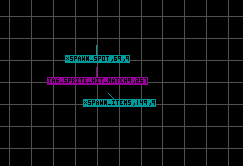 Fig 2. 2D view of sprites involved. |
2. Since this is a novice tutorial, you should know how to insert and tag sprites. So, we won't have to cover how to do that. As shown in Fig 2. above, insert two ST1 sprites. A SPAWN_SPOT (HiTag 69), and a SPAWN_ITEMS (HiTag 149). Give both of the these ST1 sprites a LoTag (match tag value) of 9. The barrel is given a LoTag of 271 for a TAG_SPRITE_HIT_MATCH. Give the barrel sprite a HiTag of 9 for our match tag value.
3. For the barrel sprite4. For the SPAWN_SPOT sprite
This is the tutorial to teach you how to create a Sounds and speaking sounds. To view this map in Shadow Warrior download speak.zip
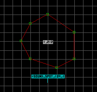 Fig 1. 2D view of sector tags and ST1 sprite. |
1. As shown in Fig 1. insert an ST1 sprite in the location where you want the sound to come from. Give this ST1 sprite a HiTag of 134 SOUND_SPOT and a LoTag of 1 for our match tag.
2. Also, from in the speak.map is a car that as a car alarm go off each time that you walk across the hood. The sector LoTag was just set to 211 for a repeat trigger effect. You can get a ideal for the available sounds from the SWSOUNDS.TXT file.

This is a tutorial to teach you how to create the Transparent Water effect through what is known as Room over Room in the Build engine. I will be starting with the water3.map created in the Swim to Another Area tutorial. You may want to have the ADVANCED.TXT sections 2 and 3 handy while going over this tutorial. To view this map in Shadow Warrior download water4.zip
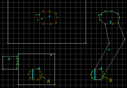 Fig 1. 2D mode view. |
1. Continuing on from the Swim to Another Area tutorial, we will need to make some changes to it for the transparent water effect to work. Sector A is our above water sector and sector B is our below water sector. Both of these sectors will have the transparent water surface. The player will not be transported between sectors A and B as they were in the Swim to Another Area tutorial. Rather, we will have a Room over Room situation. This means when the map is loaded in Shadow Warrior the underwater area will be placed in line with the above water areas. So, the heights and alignments of each of the involved sectors MUST be correct, or it will be one garbled mess. This was covered in the prior water tutorials.
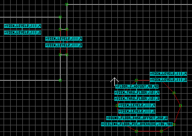 Fig 2a. Sector A. |
2. Let's work with sector A and the above water area connected with it first. We will not use the ST1 sprite HiTag 7 (SECT_DIVE_AREA). Instead, we will use the ST1 sprite HiTag 98 (FLOOR_Z_ADJUST) give it a LoTag of 40. You will use two new match tags. I will use 3 and 4. If you do not know your next available tag press F5 in 2D mode. Insert two ST1 sprites and give them both a HiTag of 121 (VIEW_THRU_FLOOR). Now give one a LoTag of 4 and the other a LoTag of 3 as shown in Fig 2a. Next, insert two more ST1 sprites in sector A and give them both a HiTag of 111 (VIEW_LEVEL2). Give one a LoTag of 4 and the other a LoTag of 3. The angle of the one with the LoTag of 4 MUST POINT DOWN (not up) for all VIEW_LEVEL2 sprites with this LoTag. To do this place the cursor on the sprite and press the > key till you get to the position you want it to be in (down in our case). Go ahead and insert two VIEW_LEVEL2 sprites in the connecting sectors with the same HiTags and LoTags as shown in Fig 2a. These connecting sectors will be seen when the player is in the water looking through the transparent surface. This is why we insert these sprites here. Again, make sure the ones with the LoTag of 4 the angle is pointing down.
Ok, back to sector A, we need to insert two more ST1 sprites. Give first one a HiTag of 202 (BOUND_FLOOR_BASE_OFFSET), and a LoTag of 0 (zero) or an even number. The second one gets a HiTag of 136 (CEILING_FLOOR_PIC_OVERRIDE) and a LoTag of 780 (water picnum).
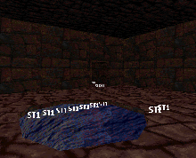 Fig 2b. Transparent shot by sector A sector. |
Go to 3D mode and change sector A floor to picnum 341. Also, keep the cursor on it and press "P" for parallax floor (flag 1).
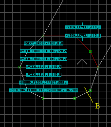 Fig 3a. Sector B area. |
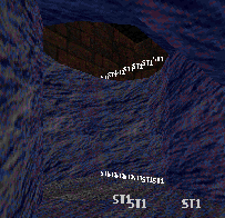 Fig 3b. Tranparent shot by sector B looking up at sector A. |
3. Now, let's work with sector B and the below water area connected with it. We will change the ST1 sprite HiTag 8 (SECT_UNDERWATER) LoTag to 0. Insert two ST1 sprites and give them both a HiTag of 120 (VIEW_THRU_CEILING). Now give one a LoTag of 4 and the other a LoTag of 3 as shown in Fig 3a. These VIEW_THRU_CEILING sprites must be in the exact same location in sector B as the VIEW_THRU_FLOOR sprites are in sector A. Next, insert two more ST1 sprites in sector B and give them both a HiTag of 110 (VIEW_LEVEL1). Give one a LoTag of 4 and the other a LoTag of 3. The angle of the one with the LoTag of 3 MUST POINT DOWN (not up) for all VIEW_LEVEL1 sprites with this LoTag. To do this place the cursor on the sprite and press the > key till you get to the position you want it to be in (down in our case). Go ahead and insert two VIEW_LEVEL2 sprites in the connecting sector with the same HiTags and LoTags as shown in Fig 3a. These connecting sectors will be seen when the player is above the water looking down through the transparent surface. This is why we insert these sprites here. Again, make sure the ones with the LoTag of 4 the angle is pointing down.
Ok, back to sector B, we need to insert two more ST1 sprites. Give first one a HiTag of 203 (BOUND_FLOOR_OFFSET), and a LoTag of 1 or an odd number (one up from the LoTag given to BOUND_FLOOR_BASE_OFFSET in sector A. This sprite needs to be in the exact same position as it's counterpart's location in sector A. The second one gets a HiTag of 136 (CEILING_FLOOR_PIC_OVERRIDE) and a LowTag of 780 (water picnum).
Go to 3D mode and change sector B ceiling to picnum 341. Also, keep the cursor on it and press "P" for parallax ceiling (flag 1).
4. Now comes the complicated stuff. Right now, the Z-coordinates of sector A floor should be the same as the Z-coordinates of sector B ceiling. Raise the ceiling of the tunnel underwater to be equal to the mirror ceiling of sector B. Now the ceiling of tunnel should have the same Z-coordinates as the mirror floor of sector A. Now raise the mirror ceiling of sector B to the same Z-coordinates as the height of the floor in the sector area A (the floor you stand on before going into the water). This will cause an overlap between sector A floor mirror and sector B mirror ceiling. If needed, read section 2.2.5 Z heights and overlap in the ADVANCED.TXT file.
Ok, now that all the sprites have been added and we have our overlap. Go to the sector A area in 3D mode and press "3". This toggles Room over Room draw in Build. Do not go to 2D mode until you have press "3" again to turn it off. If you have done everything correct so far you will get an error message if you are not standing North East of the water. If you are standing in sector A or North East of the water everything should look fine. If you picture in your mine the water area in line with the above water area, the water tunnel runs in the North East direction from the entrance hole. So, when you are standing over the water tunnel everything is fine. However, when you are not standing over the water tunnel you are standing over what is called "null space".
Go to the sector B area and press "3" while in 3D mode and see what happens down there. You will notice everything is fine until you back away from the transparent hole. At the point you get the error is where you have entered "null space" from above. This point is shown in Fig 5a and 5b as NP.
Since we intended to see the sector A area from inside the water we inserted the VIEW_LEVEL2 sprites in those above sectors as shown in Fig 2a. Everywhere we have a VIEW_LEVEL2 sprite in the above sector we must have an area below it with VIEW_LEVEL1 sprites in it. This needed below area is shown in Fig 5a and 5b as N.
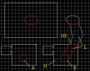 Fig 5a. Dealing with null space. |
5. To solve the above water area error, create a new sector N in the lower area. It must be at least the same size as the upper level. Use the Space Bar to do this making sure to follow around the sector B area ending up at the starting point. Choose picnum 342 for the floor and ceiling textures as shown in Fig 5b. PgUp sector N all the way to the top. Insert a pair of VIEW_LEVEL1 sprites in sector N.
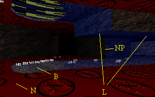 Fig 1. 3D mode view of sector B area. |
To solve the below water area error, I just added a new sector to the below water area. This is the southern L sector. Just insert a vertice on each side and connect them using the Space Bar. Then use the Space Bar and created the line at point NP. Now, lower both sectors L so you can not see the ceiling mirror in sector B.
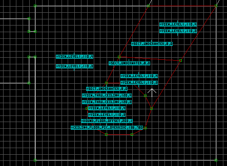 Fig 6. Area B. |
6. Insert a pair of VIEW_LEVEL1 sprites in the lower L sector as shown in Fig 6 and the SECT_UNDERWATER sprites where needed. That's pretty much all you need to do. I know it may sound like alot. Just play around with it to get a better understanding of it.
This is a tutorial to teach you how to create a basic Room-Over-Room in the Build engine. You may want to have the ADVANCED.TXT sections 2 and 3 handy while going over this tutorial. To view this map in Shadow Warrior download rmorm1.zip
1. In a Room-Over-Room situation you have an lower level and an upper level. At premap load-up, one level will be pulled over the other. This you control by setting one level to be the anchor point. This anchor point should be in the level that is part of the main map sectors. The heights and alignments of each of the involved sectors (levels) MUST be correct, or it will be one garbled mess. So, when creating your levels you have to pay special attention to the floor and ceiling z-coordinates. This can be determined by placing the cursor in a sector in 2D mode and pressing the Tab key. Picture building a house of cards. You build the bottom level then you place a ceiling on it with the cards lying flat over the lower lever. Next, you build the second level on top of the ceiling of the lower level. The z-coordinate of the ceiling of the lower level is the under side of the flat cards. However, the flat cards have a thickness to it, and the top side of the flat cards will be the z-coordinate of the floor of the upper level. The player is not transported from one level to the other since they are in perfect alignment with each other. Rather, he will fall into the lower level or climb into the upper level (if allowed). One last thing I want you to be aware of is if you look at the z-coordinates of any sector you will find that the ceiling has a lower z-coordinate number than the floor z-coordinate number. This is just the direction that the designer(s) picked.
2. Some other things you must consider when designing your Room-Over-Room situation are the size, shape, and the amount of sectors that will be involved in the process. For this tutorial we will have a hallway (hallway 1) leading to the Room-Over-Room area with a hole in the ceiling and a way to climb up to it. Also, we will have a hallway (hallway 2) leaving the upper level. For the sake of argument the lower level will be considered part of the main map level. This means we will want the lower level anchored and the upper level pulled over the lower level at premap load up. Keeping this stuff straight becomes very important when you have more than one Room-Over-Room situation within a single map.
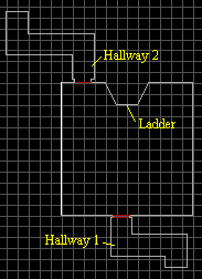 Fig 1. Lower level. |
3. Fig 1 shows the lower level of our Room-Over-Room. Even though you would have created some of your main map by this point, I wanted to show you the area that we are going to use for the lower level. The bump in the northern wall of the big room is where we will place a ladder so the player can climb up to the upper level. You will notice that both hallways are bent. This is important, and should be designed so when the player is at the far end of a hallway he can not see into the actual Room-Over-Room. The farther away that you get from the Room-Over-Room where the player can still see the actual Room-Over-Room the more complicated it becomes. So, when possible try to keep your Room-Over-Room situations in a confined area. Sometimes you can not avoid it though such as a roof situation, but still try to keep it somewhat confined. It is no biggie if you don't mind all the extra work you will put into it. Hey, it's your map go for it.
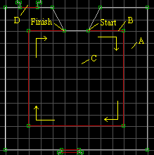 Fig 2a. Sector for hole in the ceiling. |
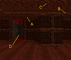 Fig 2b. 3D view of lower level. |
4. To make the hole in the ceiling we need to add another sector (peninsula sector C). Looking at Fig 2a start at the vertice marked Start (using the Space Bar in 2D mode) and make the sector ending up at the Finish vertice. If you did it correctly the line will turn red. Go into 3D mode and raise sector C ceiling up (I hit PgUp 4 times). You must keep track of the ceiling heights of sector A (the ceiling of the lower level), and sector C (hole height for the lower level). Area D is the position we plan on having the hallway (hallway 2) in the upper level. However, we must have it here to take care of the "null space" (section 2.2.3 ADVANCED.TXT) created by the Room-Over-Room effect (more on this later). Note: I used the tile number 342 for the floor and ceiling textures for area D.
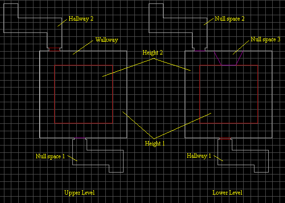 Fig 3. Both levels. |
5. Ok, create the upper level making sure that it is the exact same size as the lower level. You can do this by using the Copy and Paste, or make it manually. Just make sure that you save your work first. Sometimes it is best to save your level as different names at different stages of your level. Something like MY1.MAP, MY2.MAP, etc... Have the floor height of the upper level equal to the ceiling height of the to be hole of the first level (height 1). Now, have the floor height of the to hole of the upper level equal to the ceiling height of the lower level (height 2). This "overlap" for the to be hole is discussed in section 2.2.5 of the ADVANCED.TXT file. The texture used in this overlap (B in Figs 2a and 2b) should be the same with the same shading values. This overlap is the thickness of the flat cards I mentioned earlier (4 PgUps for lower level and 4 PgDns in the upper level). Note, that we do not want the bump in the upper level. When the player climbs the ladder in from the lower level to the upper level, we want to end up on the walkway. You will also notice that the bump in the lower level as been changed to a sector. This was done in 2D mode using the Space bar, following around to each of the vertices. When you finish all of the line (except the north wall) will turn red.
6. Null space is the area located in the oppisite level the player moves in without any VIEW_LEVEL sprites in it. It can be a void (nothing there) or a sector. You must have this area which takes the exact same space as the area in the oppisite level that the player will move through. Yes, both areas could be made for the player to past through. However, the lower levels' ceiling must be raise to the big area ceiling height (no archway or low ceiling). In our case we will discuss hallway 2 and the bump (as I call it).
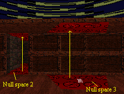 Fig 4a. 3D view of lower level facing north. |
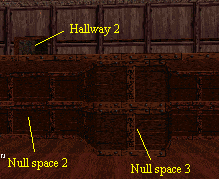 Fig 4b. 3D view of both levels pulled together. |
7. Hallway 2 is on the upper level and the player will be able to move through it. It has an archway and then the bent hallway. Null space 2 is its' counterpart on the lower level, but I made it one sector (for ease of construction). As we place in our VIEW_LEVEL sprites in one level they must be placed in the oppisite level. If we only place the VIEW_LEVEL sprites in hallway 2 and had none in the null space 2 area you would have an error and a grabled mess (in the hole area) when the player was standing in hallway 2 looking back out into the Room-Over-Room. However, once we also place the VIEW_LEVEL sprites in null space 2 it no longer is considered a "null space" and the error is corrected. Now, I hope that you can see why the bump in the lower level had to be changed to a sector. We need to put our VIEW_LEVEL sprites in it so there would not be an error when the player is standing directly over it on the walkway in the upper level. Make sure that you have the floor and ceilings of null space 2 and the null space 3 tile 342 (No Draw) texture. Now, go ahead and raise their floors all the way to the ceiling (fig 4a and 4b). In the upper level null space 1 you will have to lower the ceiling all the way to the floor with tile 342 on its' ceiling and floor too. You will notice that I made these walls blocking too by the purple colored lines (fig 3). Finally, if you haven't done so change the hole ceiling texture in the lower level and the hole floor texture in the upper level to tile number 341. Make sure that you make them parallaxing by placing the mouse cursor on them and pressing the P key in 3D mode (fig 4a).
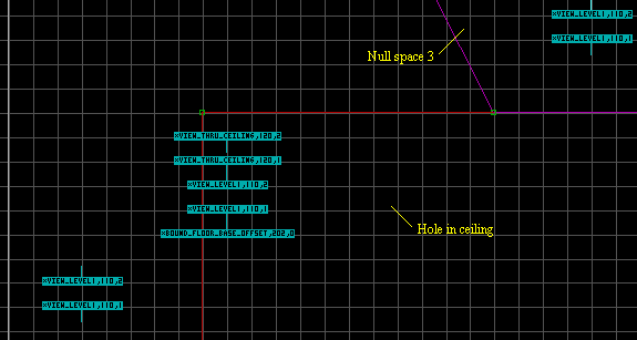 Fig 5. Entering ST1 sprites in the lower level. |
8. Ok, time to add our ST1 sprites (picnum 2307) in the lower level. Again, since we want the lower level to be part of our main map it will be the anchor level. Always start will the hole first. If you have more than one hole then pick just one and treat the other holes as any other sector on the lower level. We will use two match tags which will be 1 and 2. If you do not know your next available tag press F5 in 2D mode. Insert 5 ST1 sprites into the hole sector as shown in fig 5. Since we are in the lower level we will need the VIEW_THRU_CEILING for the first two sprites. Give them both a HiTag of 120 (Alt-H) and angle these sprites down using the > or < keys (I just do it to indicate the lower level). Give the first sprite a LoTag (Alt-T) of 2, and the second one a LoTag of 1 (our match tags). The next two sprites are given a HiTag of 110 (VIEW_LEVEL1). As before, give the first one a LoTag of 2 and the second one a LoTag of 1. The second one with the LoTag of 1 must have the angle pointing down. The fifth sprite is our anchor sprite (BOUND_FLOOR_BASE_OFFSET) Hitag 202. The Lotag must be an even number for the anchor point. So, since this is our first Room-Over-Room in this map let's give it a LoTag of 0 (zero). The positioning of the sprites with a HiTag of 120 and the last one with a Hitag of 202 is important when adding there counterparts HiTags 121 and 203 respectively in the upper level. Finally, insert two ST1 sprites in each of your other sectors in the lower level including hallway 1, and the two null spaces. Give them a HiTag of 110 and one a LoTag of 2 and the other a LoTag of 1. Remember, the one with the LoTag of 2 the angle stays up, and the one with the LoTag of 1 has the angle pointing down. These two sprites positioning are not that important as the other ones were.
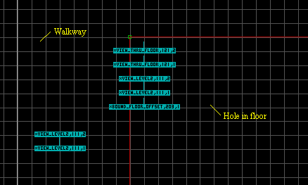 Fig 6. Entering ST1 sprites in the upper level. |
9. Ok, time to add our ST1 sprites (picnum 2307) in the upper level. Again, insert 5 ST1 sprites into the hole sector as shown in fig 6. Since we are in the upper level we will need the VIEW_THRU_FLOOR for the first two sprites. Give them both a HiTag of 121. Give the first sprite a LoTag of 2, and the second one a LoTag of 1 (our match tags). The next two sprites are given a HiTag of 111 (VIEW_LEVEL2). As before, give the first one a LoTag of 2 and the second one a LoTag of 1. The first one with the LoTag of 2 must have the angle pointing down. The fifth sprite is the BOUND_FLOOR_OFFSET (Hitag 203) sprite. The Lotag must be an odd number for the non-anchor point. So, we will add one to zero (the counterpart number) and give it a LoTag of 1. Again, the positioning of the sprites with a HiTag of 121 and the last one with a Hitag of 203 must be the same as there counterparts HiTags 120 and 202 respectively in the lower level. Finally, insert two ST1 sprites in each of your other sectors in the upper level including hallway 1, the archway, and the null space. Give them a HiTag of 111 and one a LoTag of 2 and the other a LoTag of 1. Remember, the one with the LoTag of 2 the angle points down, and the one with the LoTag of 1 has the angle pointing up.
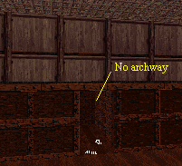 Fig 7a. 3D view facing south with no archway. |
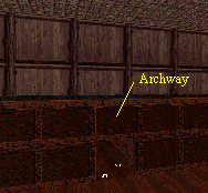 Fig 7b. Same view with archway. |
10. Ok, now that all the sprites have been added go to the lower level area. In 3D mode press "3". This toggles Room-Over-Room draw in Build. Do not go to 2D mode until you have press "3" again to turn it off. If you have done everything correct everything will look fine. Make sure that you back into the hallway and you can see fine and you get no error messages on the screen. Now press 3 to turn off the Room-Over-Room draw and go to the upper level in 2D mode. Go back to 3D mode and press 3 to turn it back on. Again, look everything over by moving all around and finding no errors. WHAT! You say that there is an error when looking down at hallway 1 in the lower level. That's right you can't see the archway and its' ceiling as been pulled up to the lower level ceiling height. This error can only be seen from the upper level looking down on the lower level. To correct this problem go to the lower level in hallway 1 and delete the sprite with the LoTag of 2. Also, delete the same sprite in the archway. Now, go to the null space 1 area and delete the same sprite (LoTag 2), and the error will be gone. This is why I use to sets of VIEW_LEVEL sprites LoTag 1 and LoTag 2 (see section 3.1 of the ADVANCED.TXT file).
 Fig 8. Bottom of ladder. |
11. Place the ladder on the bump in the lower level so the player can climb up to the upper level. Go to 3D mode and place the cursor on the wall and press the S key. The ladder picnum is 62 as shown if fig 8. You will need to place 3 ladder sprites on the wall using the PgUp and PgDn keys to arrange them vertically in 3D mode. Go to 2D mode to move them horizontally. Now, give the wall a LoTag of 305 to make it a climbing wall. Finally, insert a ST1 sprite with a HiTag of 30 (SPRI_CLIMB_MARKER) a little away from the wall. Make sure the angle is pointing out away from the wall.
It is assumed that you have gone over the Room-Over-Room 1 tutorial, and that you have an understanding of the various factors involved in creating a Room-Over-Room situation. I designed this map very similar to the exit room in The Great Escape (map 17). This is a tutorial to teach you how to create a Reflective Floor - Room-Over-Room in the Build engine. You may want to have the ADVANCED.TXT sections 2 and 3 handy while going over this tutorial. Also, it is a good ideal to print out my Flags.txt file to help you with the texture alignments. Make sure that you understand the "null space" concept which I covered in the Room-Over-Room 1 tutorial. To view this map in Shadow Warrior download rmorm2.zip
1. In any Room-Over-Room situation you have an lower level and an upper level. At premap load-up, one level will be pulled over the other. This you control by setting one level to be the anchor point. This anchor point should be in the level that is part of the main map sectors. The heights and alignments of each of the involved sectors (levels) MUST be correct, or it will be one garbled mess. So, when creating your levels you have to pay special attention to the floor and ceiling z-coordinates. This can be determined by placing the cursor in a sector in 2D mode and pressing the Tab key. Picture building a house of cards. You build the bottom level then you place a ceiling on it with the cards lying flat over the lower lever. Next, you build the second level on top of the ceiling of the lower level. The z-coordinate of the ceiling of the lower level is the under side of the flat cards. However, the flat cards have a thickness to it, and the top side of the flat cards will be the z-coordinate of the floor of the upper level. One last thing I want you to be aware of is if you look at the z-coordinates of any sector you will find that the ceiling has a lower z-coordinate number than the floor z-coordinate number. This is just the direction that the designer(s) picked.
2. Some other things you must consider when designing your Room-Over-Room situation are the size, shape, and the amount of sectors that will be involved in the process. For this tutorial we will have a hallway leading to the Room-Over-Room area with a reflective floor. For the sake of argument the upper level will be considered part of the main map level. This means we will want the upper level anchored and the lower level pulled under the upper level at premap load up. Keeping this stuff straight becomes very important when you have more than one Room-Over-Room situation within a single map. It should be noted that players, monsters and such, are not reflected in the floor. This is not an actual mirror, but the impression that it is. It is typical not to have monsters in, or able to enter a reflective floor area.
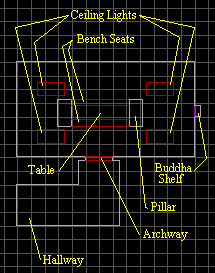 Fig 1. Upper level. |
3. Fig 1 shows the upper level of our Room-Over-Room. Even though you would have created some of your main map by this point, I wanted to show you the area that we are going to use for the upper level. You will notice that the hallway is bent. This is important, and should be designed so when the player is at the far end of the hallway he can not see into the actual Room-Over-Room area. The farther away that you get from the Room-Over-Room where the player can still see the actual Room-Over-Room the more complicated it becomes. So, when possible try to keep your Room-Over-Room situations in a confined area.
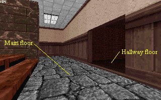 Fig 2. 3D view of the upper level. |
4a. First create your hallway coming from your main map. Second, make the archway and the main room sector. The height of the main room is 256 pixels. You can see this in 2D mode by placing the cursor in the sector and press the TAB key and read it on the lower left of the screen. Note, in fig. 2 that you must PgDn the main floor 2 times first from the height of the hallway floor. Third, make the pillars by just using the Space bar only (NO Alt-S). Forth, make the benches and table by using the Space Bar and connecting the two vertices on the northern end of the pillars (line will be white). Now, connect the two vertices on the southern end of the pillars (both lines will turn red). Insert two vertices on the inner sides of the pillars for the table. Connect these vertices for the table.
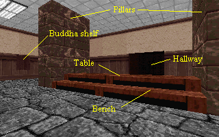 Fig 3. 3D view of upper level. |
4b. I use the PgUp key 5 times for the height of the benches, and 5 additional times on the table (in 3D mode). Basically, we DO NOT want the player to be able to see the floor on the otherside of the table (a work around error - more on this later). Create the four ceiling lights with the Space Bar and then placing your cursor inside the lights and pressing Alt-S in each one. Finally, create the Buddha shelf (place where the Buddha sprite will sit) much like you create an archway only raise the floor height too.
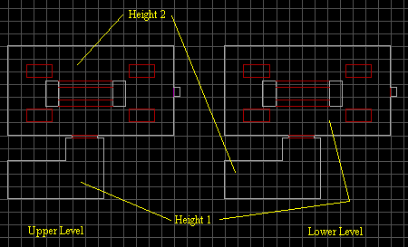 Fig 4. A 2D view of both levels. |
5. Ok, create the lower level making sure that it is the exact same size as the upper level. You can do this by using the Copy and Paste, or make it manually. Just make sure that you save your work first. Have the ceiling height (upside down floor) of the lower level main area equal to the floor height of the hallway in the upper level (height 1). Now, have the ceiling height (upside down floor) of the hallway of the lower level equal to the floor height of the upper level (height 2) main area. This "overlap" for the to be hole is discussed in section 2.2.5 of the ADVANCED.TXT file. This overlap is the thickness of the flat cards I mentioned earlier (2 PgUps for lower level and 2 PgDns in the upper level).
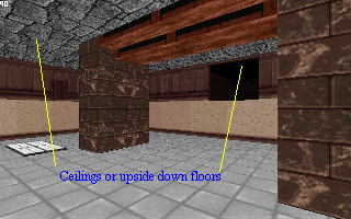 Fig 5. 3D view of lower level. |
6. All of the textures in the lower level (fig. 4) must be flipped. Go into the rmorm2.map and in 2D mode determine the flag values for the wall textures. Pay special attention to the walls on the hallway and the Buddha shelf. One note here, you can use picnum 342 (No Draw texture) for the top of the table and benches. The player will never see them, but I left the textures in for the heck of it.
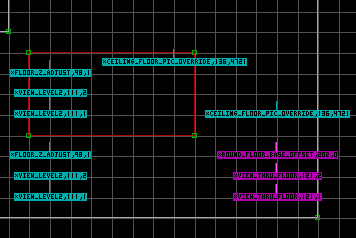 Fig 6a. Inserting ST1 sprites in upper level. |
7. Ok, time to add our ST1 sprites (picnum 2307) in the upper level in the main floor area. Again, since we want the upper level to be part of our main map it will be the anchor level. Always start will the hole first. Since we have more than one hole then pick just one and treat the other holes as any other sector on the upper level. We will use two match tags which will be 1 and 2. If you do not know your next available tag press F5 in 2D mode. Insert 7 ST1 sprites into the hole sector as shown in fig 6a. Since we are in the upper level we will need the VIEW_THRU_FLOOR for the first two sprites (purple color). Give them both a HiTag of 121 (Alt-H). Give the first sprite a LoTag (Alt-T) of 2, and the second one a LoTag of 1 (our match tags). The next two sprites are given a HiTag of 111 (VIEW_LEVEL2). As before, give the first one a LoTag of 2 and the second one a LoTag of 1. The first one with the LoTag of 2 must have the angle pointing down. The fifth sprite is our anchor sprite (BOUND_FLOOR_BASE_OFFSET) Hitag 202 (purple color). The Lotag must be an even number for the anchor point. So, since this is our first Room-Over-Room in this map let's give it a LoTag of 0 (zero). The positioning of the sprites with a HiTag of 121 and the last one with a Hitag of 202 is important when adding there counterparts HiTags 120 and 203 respectively in the lower level (these are all colored purple). The sixth sprite CEILING_FLOOR_PIC_OVERRIDE (HiTag 136) is for the actual floor texture. The LoTag is the picnum value for the texture that you want on the floor (I used 4721). Once you entered this sprite kiss the F5 option goodbye due to a designer error. If you press F5 now the next available tag would show 4722. So, now you have to manually keep track of your next tag values. Enter the following values to the HiTag 136 sprite.
The seventh sprite FLOOR_Z_ADJUST (HiTag 98) keeps the player from falling through the floor. Give this sprite a LoTag of 1. Now, insert four ST1 sprites in each of the light sectors in the upper level as shown in fig. 6a. Give them the same values as you did for the other blue sprites mentioned above.
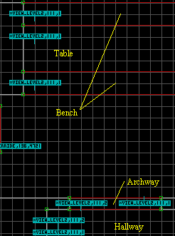 Fig 6b. Upper level. |
8. As shown in fig. 6b, insert two ST1 sprites each with a HiTag of 111 in the hallway and the archway. Finally, Insert a single ST1 sprite in each of the bench sectors and one in the table sector. Give these sprites a HiTag of 111 and a LoTag of 1. However, have the angle of these sprites point down not up like the rest with a LoTag of 1. Note, that NO ST1 sprites are inserted into the Buddha shelf sector. I placed a blocking wall here (purple line) so the player can not enter this sector. |
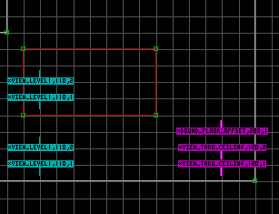 Fig 7. Inserting ST1 sprites in lower level. |
9. Enter two ST1 sprites into each sector except for the bench, table, and
Buddha sectors. Give them a HiTag of 110 (VIEW_LEVEL1)and
one a LoTag of 2 and the other a LoTag of 1. Remember, the one with the LoTag of
2 the angle stays up, and the one with the LoTag of 1 has the angle pointing
down. These two sprites positioning are not that important as the other ones
were. Next, enter the three (purple) ST1 sprites as shown in fig. 7. The
positioning of these sprites must be the same as their counterparts in the upper
level. Give the top one
BOUND_FLOOR_OFFSET (Hitag 203) and The Lotag must be an odd number for the
non-anchor point (one in our case). Give the other two sprite a HiTag of 120 and
LoTags of 2 and 1 (as shown in fig 7). Now, insert a single ST1 sprite in each
bench sector, and the table sector as we did in the upper level. Give them a
HiTag of 110 and a LoTag of 1 with their angle pointing down. Finially, change
the main floor area (including the light sectors) in the upper level to picnum
341 and make them parallaxing (P key in 3D mode). Now, do the same to the
ceiling (upside down floor) in the lower level.
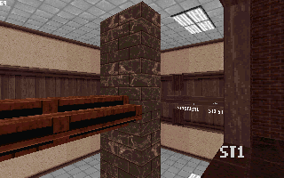 Fig 8a. 3D view in Build. |
10a. Ok, now that all the sprites have been added go to the upper level area. In 3D mode press "3". This toggles Room-Over-Room draw in Build. Do not go to 2D mode until you have press "3" again to turn it off. If you have done everything correct everything will look fine. Make sure that you back into the hallway and you can see fine and you get no error messages on the screen. You will not see the floor texture in Build. You will have to load your map in the game to see it. The error I mentioned in number 4 can be seen by going by the hallway. Put yourself in float mode (TAB twice) and press the A key until you can see the floor on the other side of the table. This will not be noticable in the actual game due to the floor texture. Basically, what is happening is you are in a sector which has two VIEW_LEVEL sprites in it looking through the benches and table which only have one VIEW_LEVEL sprite in them.
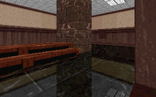 Fig 8b. Game play view. |
10b. As they say, the Room-Over-Room situation is a Hack job, and these types of problems will arise. Why just the one ST1 sprite in the bench/table area you ask. This allows this ceiling area (bench/table) to be pulled down so it can be seen. Normally, the lower level ceiling is made real high so it can not be seen from the upper level. This is why the two ST1 VIEW_LEVEL sprites are used in the other sectors. So, we can use the single sprites to be able to see the effect that we have designed here. Since we do not allow the player to enter the Buddha shelf no VIEW_LEVEL sprites are needed here. One the other hand, if the player was to be only in the lower level the the single VIEW_LEVEL sprites in the bench/table area would have had the opposite LoTag number (2 in this case). This would allow the floor of the upper lever to be pulled up. Where normally the upper level floor in made (or drawn) real low so the player can not see it from the lower level.
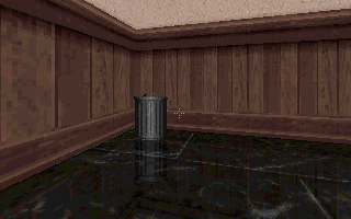 Fig 9a. View in game of a trash can. |
 Fig 9b. Same view in 2D mode upper level. |
11. Be careful when placing playable sprite in a reflective room area. If you place in items that the player can pick up, do not place them in the lower level for a reflective look. When the player picks up the item it will still be in the lower level. Fig. 9a shows a trash can and it's reflective counterpart in the lower level. You have two choices here, either make it so it can not be blown apart (and moved), or if it is shot it's counterpart is deleted from the game. We will do the latter here. First insert your sprite in the upper level, and give it a LoTag of 257 TAG_SPRITE_HIT_MATCH (Section 3.2 of SPRITAGS.TXT). Give it a HiTag of 3 (our next tag) and give it the following TAGS:
This tutorial is designed to show how create a drivable tank. It is best that you have section 4 of the ADVANCED.TXT handy while going over this turtorial. To view this map in Shadow Warrior download tank1.zip (Updated 24 March 1998).
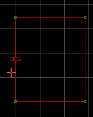 Fig 1. Main Tank object sector. |
1. First, create the sector that you plan to place your tank sector in. Next, create the outer most part of the tank (object) sector. The actual tank will be within this tank object sector (as shown in fig. 1). This I call the object sector, or main object sector. Before you create any sectors within the main object sector it is a good habit to tag one of the walls of this wall loop first (section 4.1.1). with a LoTag of 504. Make sure that you place the cursor on the outside of the wall (see fig. 1). Note: any wall of the object sector will work, but tag only one wall. It should also be noted that the floor and ceiling textures remain the same as the neighboring sector.
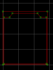 Fig 2. Creating the outer most part of the tank. |
2. Now, we start to create the actual tank itself within the outer most sector (fig. 2). The front of the tank will face to the south (towards the bottom of the picture). Go into 3D mode and raise this sector up about 13 PgUps (not the outer most sector).
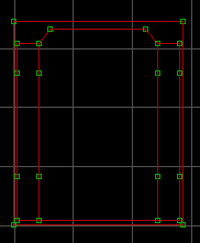 Fig 3. Adding the tank treads. |
3. By inserting vertices and connecting them using the space bar create the tread sectors.
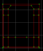 Fig 4. Dividing the treads and making the front sector. |
4. Next, divide the tread sectors so the front and back tread sectors can be sloped. Also, create the front sector that will be sloped.
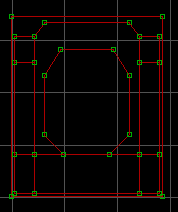 Fig 5. Outer part of turret. |
5. As shown in fig. 5, use the space bar again and make the outer part of the turret. Granted this turret will not turn independently from the tank itself. I just call it the turret.
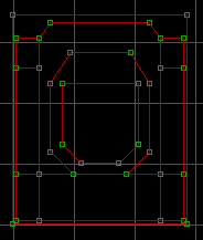 Fig 6. Creating the turret sector. |
6. Create the turret sector (fig. 6). This is where the player will be when operating the tank.
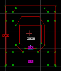 Fig 7. Tagging the turret sector. |
7. Since the player will operate the tank from the turret sector, place the cursor in this sector and give it a HiTag of 98 and a LoTag of 501. The LoTag of 501 will vary if it is not the first sector object on your map (see section 1.3 of the WALLTAGS.TXT file). Insert the gun barrel sprite (the bottom purple one). Use picnum 764 and a Flag value of 141 for the gun barrel sprite. Angle the sprite to the right for it to be in the correct position. The other two sprites shown in fig. 7 are control panel sprites that I used (not required). Make sure that you have the correct Flags for the 6 tread floor sectors (48 for non sloped and 4a for the sloped ones). This is also true for the top (floor texture) of the tank itself. Note: You can just copy them from my tank1.map using the TAB key and inserting them into yours using the Enter key (NOT the numeric pad Enter).
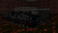 Fig 8. 3D view of our tank. |
8. When all is said and done, your tank should look something like fig 8.
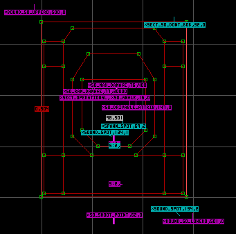 Fig 9. Inserting the main ST1 sprites for the tank to work. |
9. Insert a ST1 sprite at the very end of the gun barrel sprite, and give it a HiTag of 62 (SHOOT_POINT). Point the angle towards the front, and give TAG3, TAG5, TAG6, and BOOL1 a value of 0 (zero). TAG3 = 0 is for a tank shell, and can be given another value if you want to (see HiTag 62 in the SPRITAGS.TXT file). We need to insert seven key ST1 sprites into the turret object sector (the one that we tagged in step 7 above). If you place these ST1 sprites in a non-tagged sector the sprite(s) will have no effect. Give the first ST1 spirte a HiTag of 1 (SECT_OPERATIONAL). Give the second ST1 sprite a HiTag of 16 (SO_ANGLE) and point the angle towards the front. The third ST1 sprite is given a HiTag of 76 (SO_MAX_DAMAGE) and a LoTag value for it's health (I gave it 400). Also, set TAG3 and TAG5 to 0 (zero), and point the angle towards the front. This sprite is for the amount of damage it can take (400 in our case) from an exploding type weapon before it breaks down. We will add a spawn sprite shortly to show that it is broken. The forth ST1 sprite gets a HiTag of 147 (SO_DRIVABLE_ATTRIB) and set BOOL4 to 1. The fifth ST1 sprite is given a HiTag of 77 (SO_RAM_DAMAGE) and a LoTag of 30000. The sixth ST1 sprite has a HiTag of 134 (SOUND_SPOT) and your next match tag value 1 for our map (first match tag). Give TAG4 = 149, TAG5 = 147, and BOOL2 = 1 (very important). The seventh ST1 sprite get a HiTag of 69 (SPAWN_SPOT) and a LoTag of 2 (next match tag for map). Set TAG3 and TAG6 to 3 for smoke to appear on the turret when it becomes broken. Again, these seven ST1 sprites must go in the turret object sector.
Ok, at the top right of the first sector in step 1 insert a ST1 sprite, and give it a HiTag of 32 (SECT_SO_DONT_BOB). We need to insert two more ST1 sprites to create what is known as the Bounding Box (section 4.1.2 of the ADVANCED.TXT). This is an "imaginary rectangle" that must be large enough to contain the entire outer wall loop plus the sprites that will move with the sector object (the gun barrel and SHOOT_POINT sprites in our case). The first ST1 sprite is given a HiTag of 500 (BOUND_SO_UPPER) since it is our first sector object on the map. It is placed to the upper left of the sector object. The second ST1 sprite is given a HiTag of 501 (BOUND_SO_LOWER). You will note that this is and MUST be the same value of the LoTag given to the turret object sector in step 7 above. This sprite is placed to the lower right of the sector object. Remember, this imaginary rectangle must contain the entire outer wall loop PLUS the gun barrel and SHOOT_POINT sprites. Insert another ST1 sprite for a SOUND_SPOT (HiTag 134) somewhere within the Bounding Box (I placed it in the lower right). Give it the same match tag that you gave to the SPAWN_SPOT sprite (2 in our case). Now, give TAG4 a value of 276 (hissing sound) and BOOL2 a value of 1 (important).
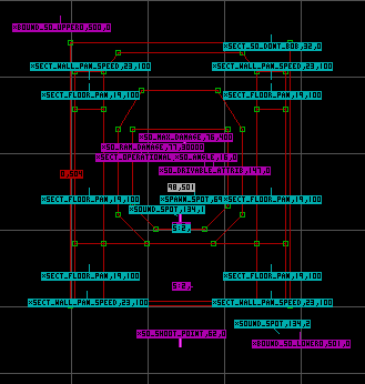 Fig 10. Inserting ST1 sprites for the treads to move. |
10. Next, we need to give the treads some movement as the tank moves. Insert a ST1 sprite in each of the tread sectors (6 in all). Give them a HiTag of 19 (SECT_FLOOR_PAN), and a LoTag of 100. Leave the angle pointing up and set BOOL1 = 1. We have to give the front and rear of the treads movement too. So, insert a ST1 sprite right next to each of the tread wall textures with the angle pointing at each wall (as shown in fig. 10). Give them a HiTag of 23 and a LoTag of 100. The ones in the front get TAG6 = 1536 and the rear get TAG6 = 512. Set all four ST1 sprites BOOL1 = 1 and you are done.
11. Finally, since I used a different palette value (4 - gray) for my floor textures (top of tank) of my tank. I needed to insert a ST1 sprite in each of the sectors with the changed palette floor value. I used HiTag 47 (SECT_DONT_COPY_PALETTE). This is not shown here, but can be found in the zipped file that you can download.
This tutorial is designed to show how fill an empty pit with diveable water to reach an upper hallway. Once you master these concepts your maps will stand out from the rest. So, take you time and experiment with them. Make sure that you save your map in various stages (i.e. My1.map, My2.map, etc.). To view this map in Shadow Warrior download fill.zip
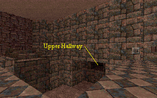 Fig 1a. Play view of the empty pit. |
1a. Within the fill.zip file (that you can download) are two maps. Fillbase.map is the base map that you can start from (empty pit). This is the base map before any ST1 sprites and Copy and Pasting has been done. Start with this map. Since you are in the Advanced section of the Build Tutorial, you should have no problems creating the fillbase.map from scratch. You will notice that there is a ladder in the pit for the player to climb out. So, there is a ST1 sprite HiTag 30 (SPRI_CLIMB_MARKER), and the wall for it has been tagged for it (LoTag 305). It should also be noted that the grate to the pit drain has been added and the key in our objective room.
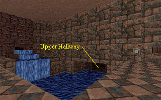 Fig 1b. Play view after the pit has been filled. |
1b. The other map found in the fill.zip file is fill.map. This is the completed map for this tutorial.
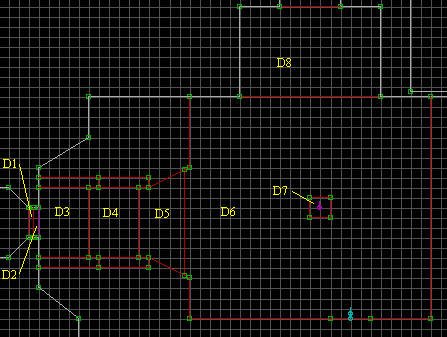 Fig 2. The Destination sectors in the empty pit area. |
2. In the empty pit area (fillbase.map) I will refer to the sectors (as shown in Fig. 2) as Destination sectors (D1 - D8) which will also be referred to as the Destination area.
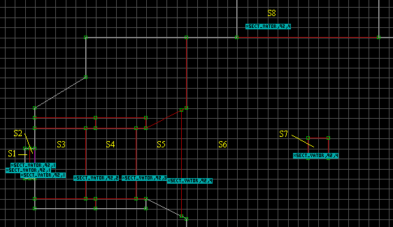 Fig 3. Creating the Source sectors. |
3. Save your map, than Copy the Destination area. I copied the upper hallway to the first step (the archway is good enough). Paste it somewhere in the void area. I pasted it to the right for tutorial purposes (Fig 4). Normally, it is pasted somewhere in a corner of the grid area. This newly pasted area will be referred to as the Source area with Source sectors S1 - S8 in it. In the Source area, delete the ST1 SPRI_CLIMB_MARKER sprite (why in a bit). Also, there are four ladder sprites (on top of each other), give them a BOOL11 = 1 (Shift + ; + 1) in 3D mode. The BOOL11 will keep these ladder sprites stationary when the floor moves later on. Before we go any further, Copy Source sectors S6, S7, and S8 and paste them somewhere in the void area. This newly pasted area will be referred to as the Dive Area (Fig 4).
Now delete the grate sprite from the S7 sector in the Source area, and raise the floor height level with the S6 sector. Give all of the floor textures for S1 - S8 a picnum of 780. You may have to flip (F key a couple of times) these water textures so the flow is going the same direction as in the tunnel. Give the wall textures between S3 and S4, S4 and S5, S5 and S6 and picnum of 300. When the Source area is copied into the Destination area this water will appear, but we want the water to raise up as it pours in. So, we will treat these sectors as floor to ceiling doors some triggering the next to raise in sequence.
Insert a ST1 sprite in the S1 thru S8 sectors. Give all of them a HiTag of 92 (SECT_VATOR). Give S1, S2, and S3 ST1 SECT_VATOR sprites a LoTag of 1 (our first match tag). S4 and S5 ST1 SECT_VATOR sprites get a LoTag of 2 and 3 respectively. Finally, S6, S7, and S8 get a LoTag of 4.
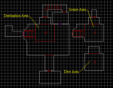 Fig 4. Positioning of the areas in the Fill.map. |
4. For now, we will not worry about the Dive Area. We need to work on the other two areas to make sure that they work alright first.
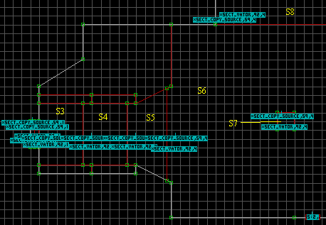 Fig 5a. Inserting sprites into the Source Area. |
5a. Insert a ST1 sprite in each of the Source sectors. Give them a HiTag of 59 (SECT_COPY_SOURCE), and a LoTag of the SECT_VATOR in that sector. Give each SECT_COPY_SOURCE sprite a TAG3 starting with a value of 1 for the S1 sprite through TAG3 = 8 for the S8 SECT_COPY_SOURCE sprite.
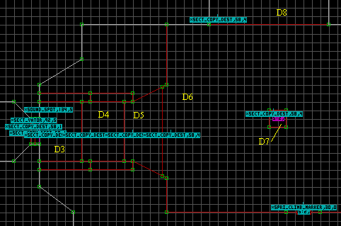 Fig 5b. Inserting sprites into the Destination Area. |
5b. Ok, insert a ST1 sprite in each of the Destination sectors. Give them a HiTag of 58 (SECT_COPY_DEST), and as in step 5a the same LoTag that was given in each of the S1 thru S8 sectors (i.e. D1 thru D3 SECT_COPY_DEST sprites get a LoTag of 1, D4 sprite gets a LoTag of 2, and so on). Important, the TAG3 values of the SECT_COPY_DEST sprites must match the TAG3 value of the SECT_COPY_SOURCE sprites in the counterpart sector (i.e. D5 SECT_COPY_DEST sprite TAG3 = 5 and the S5 SECT_COPY_SOURCE sprite TAG3 = 5).
 Fig 6. Inserting sprites into the Destination Area. |
6. Insert a ST1 sprite in the tunnel off of the Destination area. Give it a HiTag of 92 and a LoTag of 4. Give TAG3 = 1, TAG4 = 16, and BOOL1 = 1. Use the PgUp key and raise the distance of this sprite the same distance between the SECT_VATOR sprite in S6, S7, or S8 and their floor. Insert a ST1 sprite into the D1 sector and give it a HiTag of 92 and a new match tag LoTag of 5 (in our case).
Though the map is not done yet, you need to test your map at this point to make sure everything is working properly.
When a Source sector is copied into a Destination sector all of the visible sprites are removed (except for getable items). All wall tags are removed too. The ST1 sprites are not removed. This is why the SPRI_CLIMB_MARKER ST1 sprite was not place in the Source sector, but the ladder sprites and wall tag were left in. This is also why no BOOL11 = 1 was set for the ladder sprites in the Destination sector because these ladder sprites will be removed when the Source sectors is copied into the Destination sectors. Assuming that your map is working fine we will now continue on.
 Fig 7. A 3D view of the Dive Area. |
7. Go to the Dive area and delete the two top ladder sprites leaving the two bottom ladder sprites. Make sure that these ladder sprites BOOL11 is set to 1. Also, make sure that the grate sprite BOOL11 is set to 1. Change the ceiling texture to the water picnum 780, and make sure that it is moving in the same direction as the surface in the Source sectors. Since the ceiling will be moving you need to orient the walls (O key in 3D mode). Lower the ceiling to the same height as the SECT_VATOR sprites in the S6, S7, and S8 sectors. Move the grate sprite out of the way and change the floor texture to the same surrounding floor texture. Insert a ST1 sprite in each of the three sectors and flip them upside down (F twice). For now, raise the ST1 sprite in the drain sector even with the surrounding floor heights. Now, lower the floor of this sector way down so the player can't see it to well (if at all). Set the palette (Alt-P) to 9 for everything (walls, ceilings, floors, and sprites but not the ST1 sprites). Darken the floors and walls by about three or so levels. Now, move the grate sprite back over the hole (if you haven't already done so). Give these ST1 sprites a HiTag of 92 (SECT_VATOR) and a LoTag of 4.
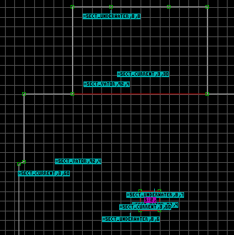 Fig 8. A 2D view of the Dive Area. |
8. Insert a ST1 sprite into each of the three dive sectors and give them a HiTag of 8 ( SECT_UNDERWATER). Note your positioning of these sprites for when you insert the SECT_DIVE_AREA sprites in sectors S6, S7, and S8 their placement MUST BE the same. Give the SECT_UNDERWATER sprites LoTag your next match tags (6, 7, and 8 in our case). For effect, insect a ST1 sprite in each of the Dive sectors and give them a HiTag of 3 (SECT_CURRENT). I like to have the current under water a little slower than the current on the surface. As shown in Fig 8, give the SECT_CURRENT sprites a LoTag of 60, and 30 for the upper SECT_CURRENT sprite LoTag. Point the angle of the SECT_CURRENT sprites to the right (the direction we want the current to flow).
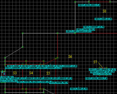 Fig 9. A 2D view of the Source Area. |
9. In the Source area, insert a ST1 sprite into sectors S6, S7, and S8 paying close attention that their position is the same as the SECT_UNDERWATER sprites in the Dive area. Give them a HiTag of 7 ( SECT_DIVE_AREA) and the same LoTags as their counterparts in the Dive area sectors (6, 7, and 8 in our case). Now, insert a ST1 sprite into sectors S3 thru S5 and give them a LoTag of 30 while leaving their HiTags at 0 ( SECT_SINK). Insert a ST1 sprite into sectors S6 thru S8 and give them a LoTag of 40 leaving their HiTags at 0 (SECT_SINK). Finally, insert a ST1 sprite into sectors S3 thru S8 and give them a HiTag of 3 (SECT_CURRENT). Point their angles to the right as we did in step 8. Give the SECT_CURRENT sprites in sectors S3 thru S5 a LoTag of 180, in sectors S6 and S7 a LoTag of 80, and in sector S8 a LoTag of 40.
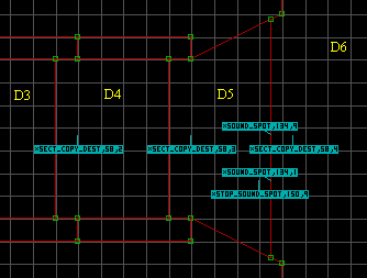 Fig 10. A 2D view of the Destination Area. |
10. The last thing that I want to show you is inserting two different sounds. One for the water pouring in (Waterfall1), and the other is a slower water sound (Waterflow1). In sector D5 of the Destination area, insert three ST1 sprites, and raise them off the floor by about 12 PgUps. Give to of them a HiTag of 134 (SOUND_SPOT) and the other one a HiTag of 150 (STOP_SOUND_SPOT) as shown in Fig 10. One SOUND_SPOT sprite gets a LoTag of 1 and the other gets a LoTag of 9 (our next match tag). Give the following values to the SOUND_SPOT sprites.
This tutorial is designed to show how create a remote sector object. It is best that you have section 4 of the ADVANCED.TXT handy while going over this turtorial. To view this map in Shadow Warrior download remote.zip
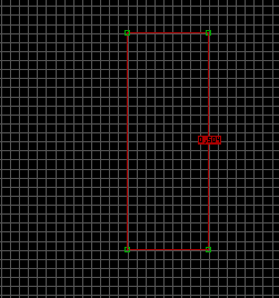 Fig 1. 2D mode of Main Sector Object tagged. |
1. By now you should have a good understanding for creating sector objects. The rules remain the same. For this tutorial I created the little train that is found in the first map ($BULLET.MAP). If you need the same effect for getting a key then look at the first map. The area for the cars to drive on is one sector. Sprites were used as an upper wall for the car to drive under so the player could get the key. As always, we need to create the main area where the sector object will be place in. Give this four wall outer loop a LoTag of 504 (on one of the walls only) as shown in Fig 1.
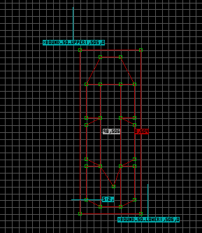 Fig 2. 2D mode view of sector object and basic tags and sprites. |
2. Once you have created the inner sectors for appearance (as shown in fig. 2) we need to tag the center sector with a HiTag of 98 (Operational) and a LoTag of 506 (TAG_OBJECT_CENTER). I'm using 505 so you will see a 1 when we do the SECT_SO_BOUNDING sprites. Note: make sure that you give the top (floor textures) of the sector object itself has the Relative Floor to the on position (R key in 3D mode). As shown, insert two ST1 sprites for the BOUND_SO_UPPER (LoTag 505) and BOUND_SO_LOWER (LoTag 506). This will give a value of 1 right after their names in the sprite blue rectangle. Remember your value if it is different due to different LoTag values. For appearance sake I inserted an antenna sprite.
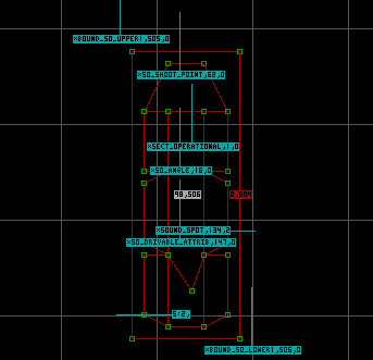 Fig 3. Inserting the ST1 sprites. |
3. We need to insert five key ST1 sprites into our the remote object sector (as shown in Fig. 3). Give the first ST1 spirte a HiTag of 62 (SO_SHOOT_POINT) and point the angle towards the front of the sector object. Also, give the SO_SHOOT_POINT a TAG3 value of 255 which make the player's weapon go away. Give the second ST1 sprite a HiTag of 1 (SECT_OPERATIONAL) and point the angle towards the front. The third ST1 sprite is given a HiTag of 16 (SO_ANGLE), and point the angle towards the front. The forth ST1 sprite HiTag 134 (SOUND_SPOT) is for the sound that our remote sector object will make when it is moved. Set TAG4 to 0 and give it a LoTag your next matched tag. I our case we have not used 2 yet so that what I used. Give TAG5 a value of 402 for the movement sound. Also, give BOOL2 a value of 1 so the sound_spot will follow with our sector object. The final ST1 sprite get a Hitag of 147 (SO_DRIVABLE_ATTRIB) again with the angle pointing towards the front. Give TAG6 a value of 3600 for the movement speed, BOOL1 and BOOL4 a value of 1.
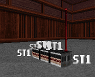 Fig 4. 3D mode view. |
4. Ok, we now have the sector object all setup and ready for the remote part of it.
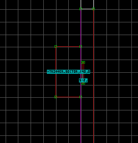 Fig 5. 2D mode view. |
5. As shown in Figs. 5 and 6, make a narrow sector for the control panel. This control panel is only for looks. Again, for appearance sake I inserted an antenna sprite on top on this control panel. Create a sector in front of the control panel for the player to stand on. Insert a ST1 sprite into this sector and give it a Hitag of 140 (TRIGGER_SECTOR).
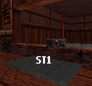 Fig 6. 3D mode view of control panel. |
6. There you have it, a simple remote sector. Experiment with it to get the effect that you require.
END